Electricity — AQA GCSE Study Guide
Exam Board: AQA | Level: GCSE
Master the fundamental differences between series and parallel circuits. This topic is a guaranteed mark-earner in your GCSE Physics exam, covering the essential rules for current, potential difference, and resistance that form the basis of all electrical engineering.
## Overview
Electricity is the lifeblood of the modern world, and understanding how it flows through different circuits is one of the most fundamental concepts in Physics. This topic, focusing on Series and Parallel Circuits (Specification reference 4.2), explores the rules governing current, potential difference (voltage), and resistance.
Why is this important? Because examiners love to test your ability to apply these rules. They will present you with circuit diagrams and ask you to calculate missing values or explain why a bulb has gone out. This topic connects heavily to energy transfers and Ohm's Law. By mastering the distinct rules for series and parallel configurations, you will unlock a significant portion of the marks in your electricity paper.

*Listen to the 10-minute audio guide for a complete walkthrough of this topic.*
## Key Concepts
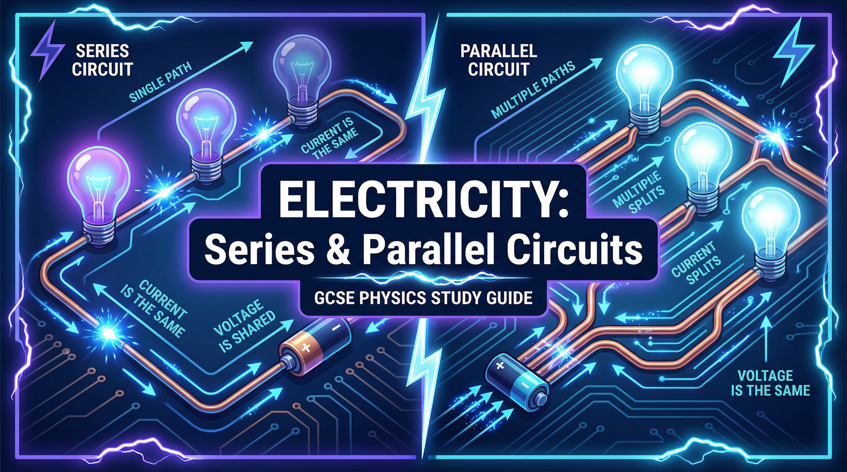
### Concept 1: Series Circuits - The Single Path
A series circuit is like a single-lane road with no turn-offs. Every electron that leaves the battery must travel through every component in the circuit to get back to the battery.
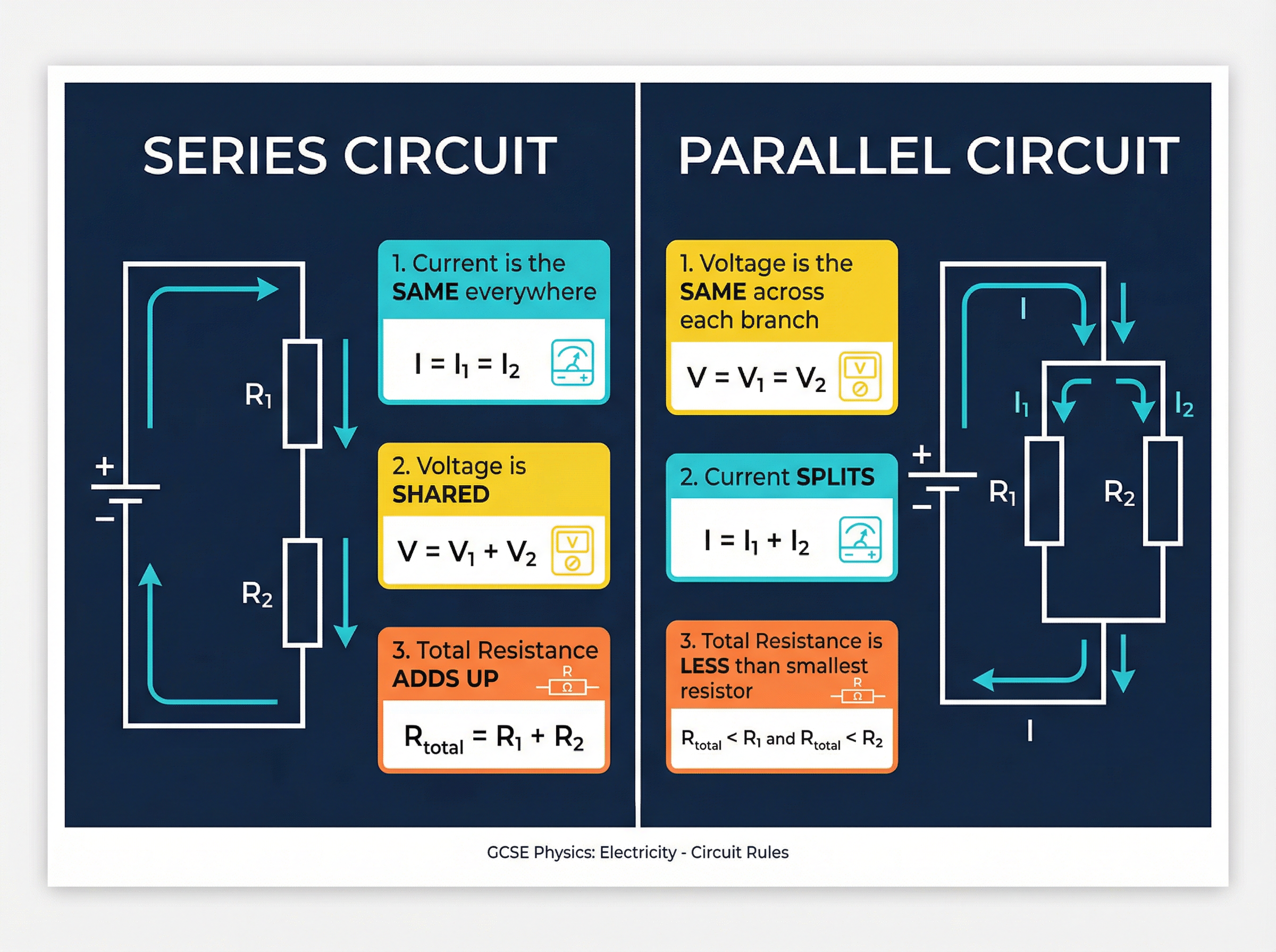
Because there is only one path, the **current is the same everywhere**. If an ammeter reads 2A next to the battery, it will read 2A between the resistors, and 2A after the last resistor. However, the **potential difference (voltage) is shared** between the components. The battery provides the total 'push', and each component uses a portion of it. The total resistance of a series circuit is simply the sum of all individual resistances. Adding more resistors in series increases the total resistance, which means the total current will decrease.
**Example**: A 12V battery is connected in series with a 4Ω resistor and a 2Ω resistor. The total resistance is 4 + 2 = 6Ω. The current everywhere is I = V/R = 12/6 = 2A. The voltage across the 4Ω resistor is V = I × R = 2 × 4 = 8V. The voltage across the 2Ω resistor is V = 2 × 2 = 4V. Notice that 8V + 4V = 12V (the total voltage is shared).
### Concept 2: Parallel Circuits - The Multiple Paths
A parallel circuit is like a motorway with multiple lanes. When electrons reach a junction, the path splits. Some electrons take one branch, while others take another.
Because the branches are connected directly across the power supply, the **potential difference is the same across every branch**. If you have a 12V battery, every branch receives 12V. However, the **current splits** at the junctions. The total current leaving the battery is the sum of the currents in each separate branch.
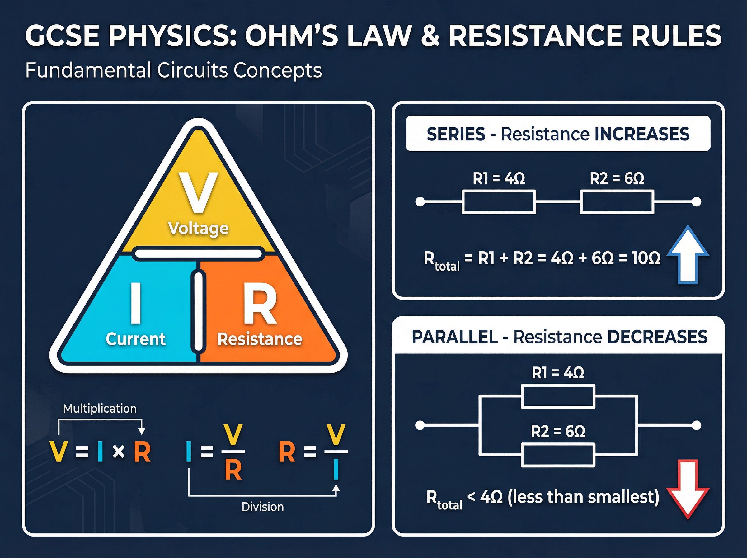
The most counter-intuitive rule is about resistance: **adding resistors in parallel decreases the total resistance**. Why? Because you are providing *more paths* for the current to flow. It's like opening more checkout lanes at a supermarket; the overall resistance to the flow of customers decreases. The total resistance of a parallel circuit is always less than the resistance of the smallest individual resistor.
### Concept 3: Ohm's Law and Calculations
Ohm's Law states that the current through a conductor is directly proportional to the potential difference across it, provided the temperature remains constant. The formula is V = I × R.
Examiners will frequently ask you to combine your knowledge of series/parallel rules with Ohm's Law. You must be comfortable rearranging the formula to find V, I, or R.
## Mathematical/Scientific Relationships
- **V = I × R**
- **V**: Potential Difference (Voltage) measured in Volts (V).
- **I**: Current measured in Amperes (A).
- **R**: Resistance measured in Ohms (Ω).
- *Must memorise.*
- **Series Circuits**:
- Current: $I_{total} = I_1 = I_2 = ...$
- Voltage: $V_{total} = V_1 + V_2 + ...$
- Resistance: $R_{total} = R_1 + R_2 + ...$
- **Parallel Circuits**:
- Current: $I_{total} = I_1 + I_2 + ...$
- Voltage: $V_{total} = V_1 = V_2 = ...$
- Resistance: $R_{total} < R_{smallest}$ (Higher Tier: $\frac{1}{R_{total}} = \frac{1}{R_1} + \frac{1}{R_2} + ...$)
## Practical Applications
Understanding these circuits is vital for real-world applications.
- **Domestic Wiring**: Your house is wired in parallel. This ensures that every appliance receives the full 230V mains supply, and if one appliance breaks or is switched off, the others continue to work because they are on separate branches.
- **Fairy Lights**: Older Christmas tree lights were wired in series. If one bulb blew, the circuit was broken, and all the lights went out. Modern sets use parallel or a combination to avoid this.
- **Required Practical**: You may be asked to investigate the relationship between resistance and length of wire (series), or how adding resistors in series vs parallel affects total resistance. Apparatus includes a power supply, ammeter (always in series), voltmeter (always in parallel across the component), and resistors.