Energy, Power and Resistance — OCR A-Level Study Guide
Exam Board: OCR | Level: A-Level
This guide provides a comprehensive overview of the OCR A-Level Physics topic 'Energy, Power and Resistance' (4.2). It covers the key concepts of e.m.f., potential difference, resistivity, and power, with a focus on exam technique and common pitfalls to help students secure maximum marks.
## Overview
Welcome to the essential guide for OCR A-Level Physics, module 4.2: Energy, Power, and Resistance. This topic forms the bedrock of all circuit analysis and is a frequent star in exam papers. It explores how energy is transferred in electrical circuits, why materials resist the flow of electricity, and how to calculate the power dissipated by components. A solid grasp of these principles is not just crucial for exam success but also for understanding everything from the wiring in your home to the complex electronics in your phone. This guide will break down the core concepts, provide you with the tools to tackle challenging calculations, and highlight the subtle distinctions that examiners use to separate top candidates. We will delve into the microscopic behaviour of electrons, analyse the characteristics of different components, and master the art of applying the correct formula in the right situation. Expect to see questions ranging from simple definitions (AO1) to complex data analysis and multi-step calculations (AO2 & AO3).

## Key Concepts
### Concept 1: Electromotive Force (e.m.f.) and Potential Difference (p.d.)
At first glance, e.m.f. (symbol ε) and p.d. (symbol V) seem similar – both are measured in Volts (V), which are equivalent to a Joule per Coulomb (JC⁻¹). However, they describe opposite energy transformations, a distinction that is vital for exam marks. **Electromotive force (e.m.f.)** is the energy transferred *from* a source (like a battery or power supply) *to* electrical energy, per unit charge. It is the work done *on* the charge carriers to energise them. Think of it as the total energy parcel given to each coulomb of charge at the start of its journey.
**Potential Difference (p.d.)**, in contrast, is the energy transferred *from* electrical energy *to* other forms (like heat, light, or sound) as charge passes *through* a component. It is the work done *by* the charge carriers as they move through the circuit. It represents the energy 'dropped off' at each component.
**Example**: A 12V battery has an e.m.f. of 12V. This means it provides 12 Joules of energy to every Coulomb of charge that leaves it. If this charge then flows through a bulb with a p.d. of 12V across it, the bulb will dissipate 12 Joules of energy for every Coulomb that passes through it, converting it into light and heat.
### Concept 2: Resistance and Resistivity
Resistance (R) is a measure of how difficult it is for current to flow through a component. It is defined by the equation **R = V/I**. An ohmic conductor has a constant resistance, provided physical conditions like temperature remain constant.
However, the resistance of a component depends on its physical properties. This is where **resistivity (ρ)** comes in. Resistivity is an intrinsic property of a material that quantifies how strongly it resists electric current. A material with low resistivity, like copper, is a good conductor, while a material with high resistivity, like rubber, is a good insulator. The relationship is given by the formula:
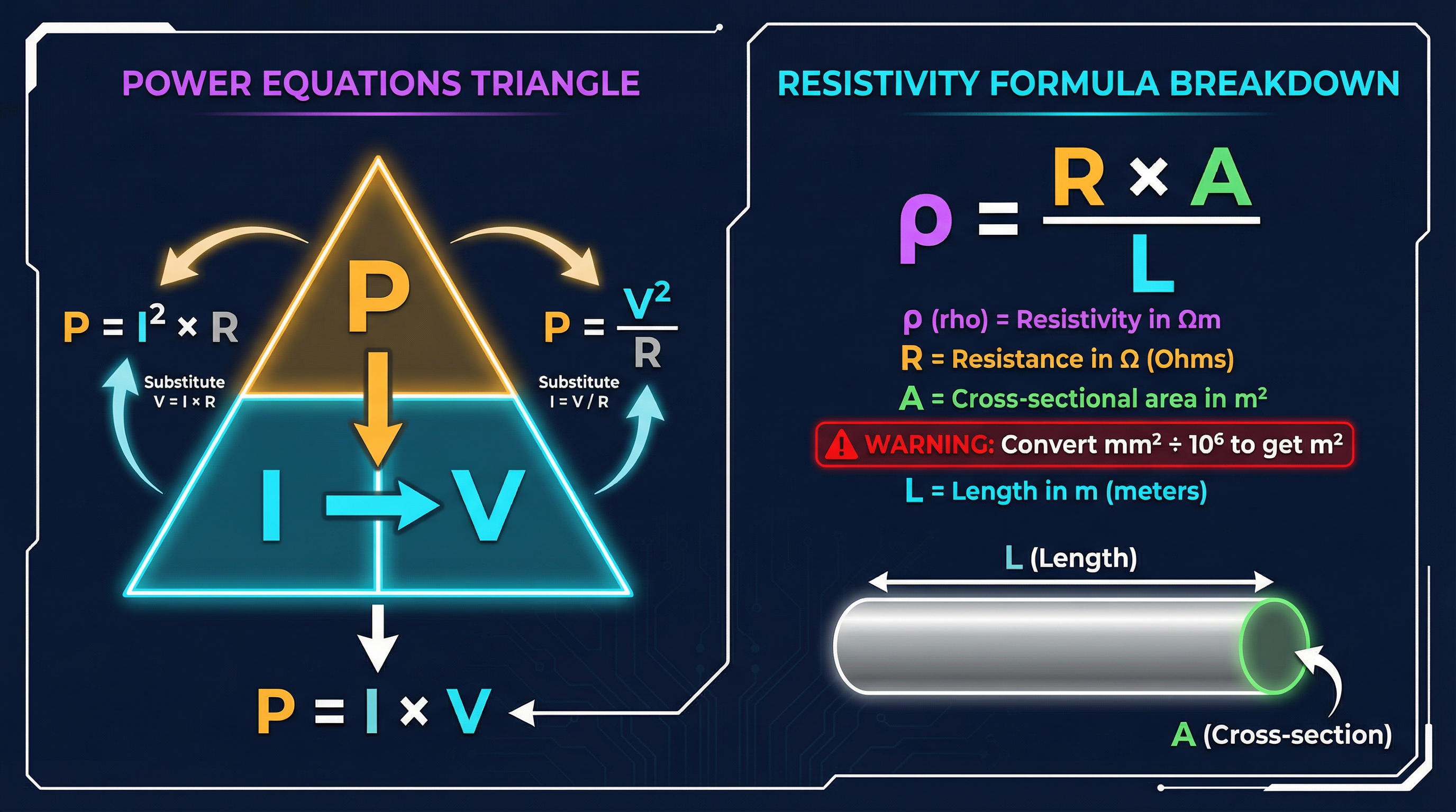
**ρ = RA/L**
- **ρ**: Resistivity of the material (in Ωm)
- **R**: Resistance of the wire (in Ω)
- **A**: Cross-sectional area of the wire (in m²)
- **L**: Length of the wire (in m)
Examiners frequently test the manipulation of this formula, especially the conversion of units. The most common mistake is failing to convert the cross-sectional area from mm² to m². Remember: 1 mm = 10⁻³ m, so 1 mm² = (10⁻³)² m² = 10⁻⁶ m². You must divide by one million!
### Concept 3: Power Dissipation
Power (P) is the rate at which energy is transferred. In electrical circuits, it is the energy dissipated by a component per second, measured in Watts (W). The primary equation for power is:
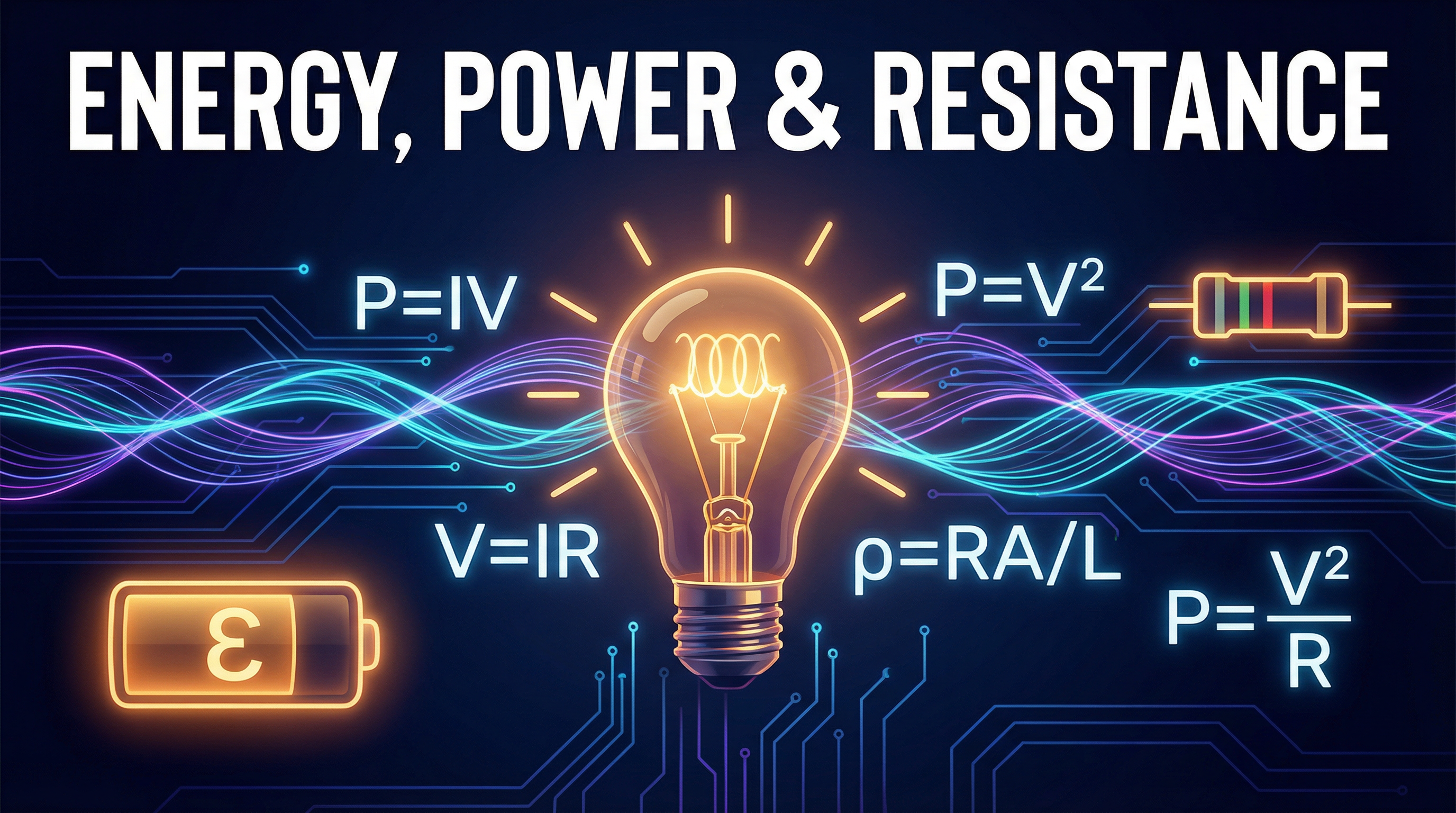
**P = IV** (Power = Current × Voltage)
This formula can be combined with Ohm's Law (V=IR) to derive two other essential forms:
1. **P = I²R**: Derived by substituting V = IR into P = IV. This equation is particularly useful for calculating the power lost as heat in transmission lines, where the current is the same throughout.
2. **P = V²/R**: Derived by substituting I = V/R into P = IV. This is ideal for analysing components in parallel, where the voltage across each is the same.
Candidates must be able to select the most appropriate equation for a given scenario to solve problems efficiently.
### Concept 4: I-V Characteristics
An I-V characteristic graph shows how the current (I) through a component varies as the potential difference (V) across it is changed. The shape of this graph reveals important information about the component's resistance.
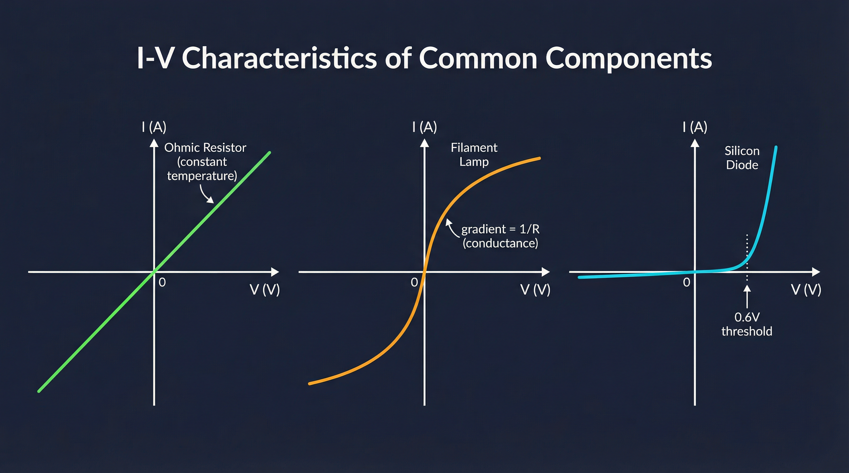
- **Ohmic Resistor**: At a constant temperature, the current is directly proportional to the voltage (Ohm's Law). The I-V graph is a straight line through the origin. The resistance is constant, and its value is 1/gradient (if I is on the y-axis).
- **Filament Lamp**: The graph is a curve that becomes less steep as the voltage increases. As voltage rises, the current increases, causing the filament to heat up. This increased temperature causes the metal lattice ions to vibrate more vigorously, obstructing the flow of electrons and thus increasing resistance. A shallower gradient on an I-V graph signifies a higher resistance.
- **Diode**: A semiconductor device that allows current to flow in only one direction (forward bias). The graph is essentially flat (very high resistance) for negative voltages, and then shows a sharp increase in current after a certain positive threshold voltage (typically ~0.6V for a silicon diode). In reverse bias, the resistance is extremely high, but not infinite.
## Mathematical/Scientific Relationships
- **Ohm's Law**: V = IR (Must memorise)
- **Resistivity**: ρ = RA/L (Given on formula sheet)
- **Power Equations**:
- P = IV (Must memorise)
- P = I²R (Can be derived, but useful to memorise)
- P = V²/R (Can be derived, but useful to memorise)
- **Charge and Current**: Q = It (Must memorise)
- **Energy and Power**: E = Pt (Must memorise)
- **Energy and Voltage**: E = VQ (Derived from E=Pt and Q=It)
- **Kilowatt-hour (kW⋅h)**: A unit of energy. 1 kW⋅h = 3.6 MJ. To calculate energy in kW⋅h, power must be in kW and time must be in hours. (Must memorise conversion and application).
## Practical Applications
This topic is directly assessed in the **Required Practical: Determining the resistivity of a wire**.
- **Apparatus**: A length of resistance wire (e.g., nichrome), a micrometer screw gauge, a ruler, a power supply, an ammeter, and a voltmeter.
- **Method**:
1. Measure the diameter of the wire at several points using the micrometer and calculate the mean diameter. Halve this to find the radius (r) and calculate the cross-sectional area (A = πr²).
2. Set up a circuit with the power supply, ammeter in series with the wire, and voltmeter in parallel across a measured length (L) of the wire.
3. Record the current (I) and voltage (V) for a specific length L.
4. Calculate the resistance (R = V/I) for that length.
5. Repeat for several different lengths of the wire.
6. Plot a graph of Resistance (R) on the y-axis against Length (L) on the x-axis. This should be a straight line through the origin.
7. The gradient of this graph is R/L. From the resistivity equation, ρ = RA/L, we can see that ρ = gradient × A.
- **Common Errors**: Inconsistent contact points when measuring length; parallax error when reading the ruler; not accounting for zero error on the micrometer; allowing the wire to heat up, which would change its resistance.
- **Exam Focus**: Examiners may ask you to critique a student's method, suggest improvements, or analyse a given set of results, including plotting the graph and calculating the resistivity.