Current — OCR GCSE Study Guide
Exam Board: OCR | Level: GCSE
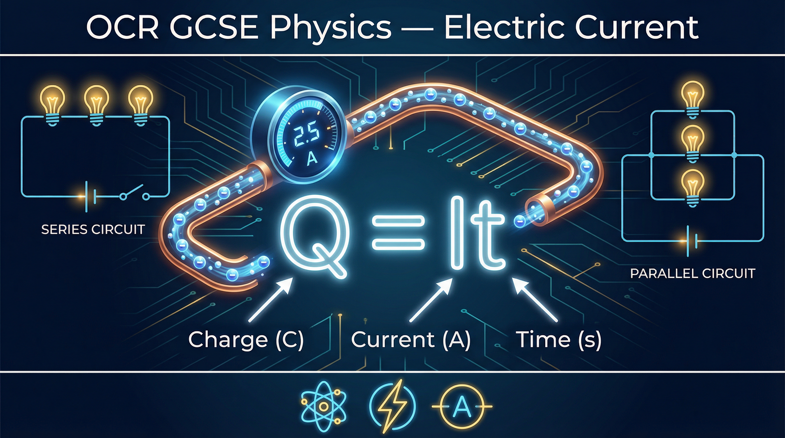
Master the fundamentals of electric current for your OCR GCSE Physics exam. This guide breaks down the core concepts of charge, current in series and parallel circuits, and the essential Q=It equation, providing examiner insights to help you secure every mark.
## Overview
Electric current is one of the foundational pillars of physics, describing the flow of electrical charge that powers our world. For your OCR GCSE Physics exam (specification reference 3.1), a thorough understanding of current is not just essential for this topic but forms the bedrock for understanding voltage, resistance, and power. Examiners frequently test the definition of current, the application of the core equation Q = It, and the behaviour of current in both series and parallel circuits. Candidates who can move beyond simple definitions to explain *why* current behaves as it does, using principles like the conservation of charge, are those who access the highest marks. This guide will equip you with the precise language, calculation skills, and exam techniques required to confidently tackle any question on electric current, from simple definitions to more complex, multi-step problems involving circuit analysis.

## Key Concepts
### Concept 1: The Definition of Current
At its heart, electric current is the measure of how much electrical charge is flowing past a point in a circuit every second. To secure the mark in an exam, you must be precise. The definition that examiners are looking for is: **Current is the rate of flow of charge.** It is crucial to include the words 'rate of flow' as this implies a quantity over time, which is the essence of current. Simply stating 'the flow of electrons' is a common mistake and will not be awarded credit, as it is not specific enough and doesn't encompass the concept of 'rate'.
* **Charge (Q)** is a fundamental property of matter, measured in **Coulombs (C)**.
* **Current (I)** is the rate of flow of this charge, measured in **Amperes (A)**, often shortened to 'Amps'.
* **Time (t)** is measured in **seconds (s)**.
Think of a river: the total amount of water is the charge, and the speed at which the water flows past you is the current. A higher current means more charge is passing a specific point in the wire each second.
### Concept 2: Conventional Current vs. Electron Flow
Historically, scientists defined the direction of current flow before the electron was discovered. They established a convention that current flows from the **positive terminal** of a power source to the **negative terminal**. This is known as **conventional current**. We now know that in metal wires, the charge carriers are negatively charged electrons, which are repelled from the negative terminal and attracted to the positive one. Therefore, **electron flow** is actually from negative to positive. For your exam, unless a question specifically asks about electron flow, you should always use and draw the direction of **conventional current**.
### Concept 3: Current in Series Circuits
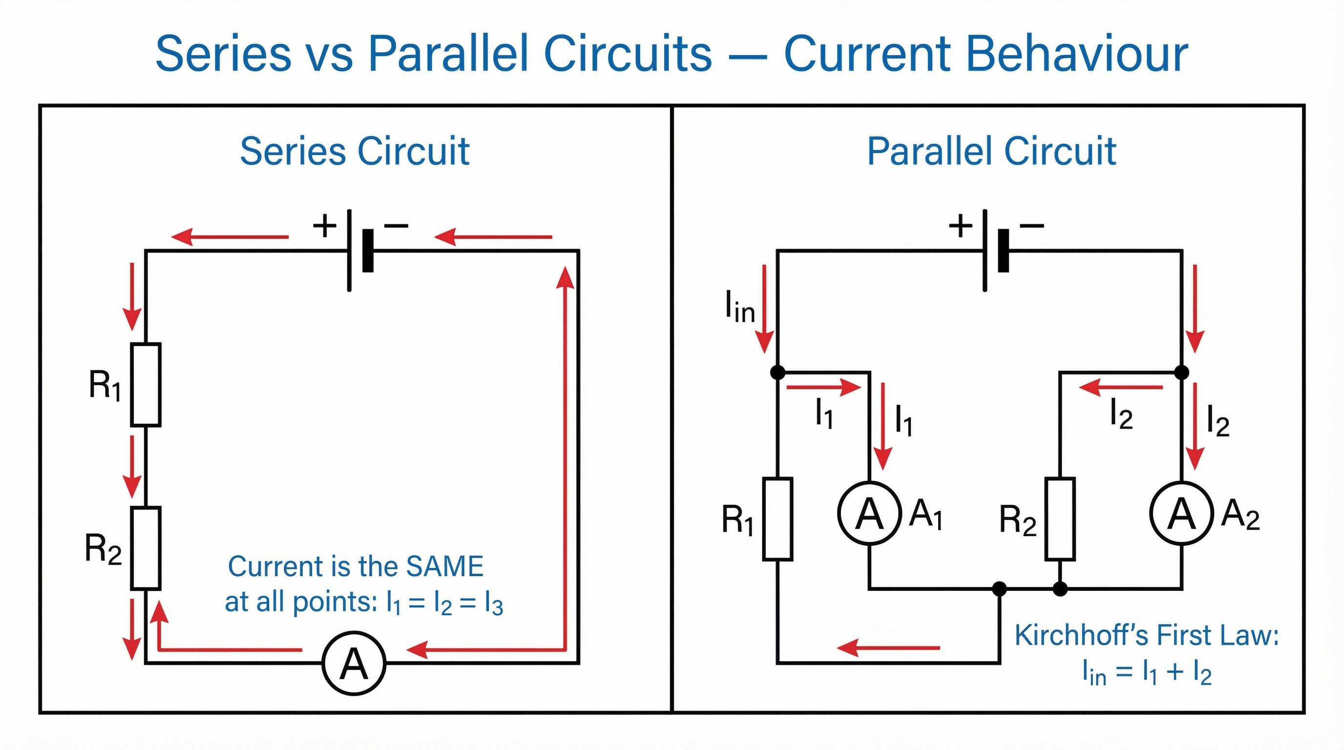
In a series circuit, components are connected end-to-end, forming a single, unbroken loop. There is only one path for the charge to take. A fundamental rule, based on the **conservation of charge**, is that **the current is the same at all points in a series circuit**. Charge is not 'used up' or consumed as it passes through components like resistors or bulbs. The number of electrons flowing past point A per second is identical to the number flowing past point B. An ammeter placed anywhere in a series circuit will give the same reading.
### Concept 4: Current in Parallel Circuits (Higher Tier)
In a parallel circuit, the circuit splits into two or more branches, providing multiple paths for the current. At a junction where the circuit divides, the total current flowing into the junction must equal the total current flowing out of it. This is known as **Kirchhoff's First Law**, and it is another application of the conservation of charge. The current splits between the branches, with the amount of current in each branch depending on its resistance (a topic covered in 3.2). If you add up the currents in all the parallel branches, the total will be the same as the current that left the battery.
**Example**: If 5A flows from the battery and the circuit splits into two branches, 2A might flow through one branch and 3A through the other. The sum (2A + 3A = 5A) is equal to the total current.
### Concept 5: Measuring Current
To measure the current flowing through a component, you must use an **ammeter**. An ammeter must always be connected **in series** with the component. This means you have to break the circuit and place the ammeter into the loop, so that the current you want to measure flows *through* it. Connecting an ammeter in parallel is a critical error that will cause a short circuit and will not measure the current correctly. An ideal ammeter has zero resistance so that it does not affect the current it is measuring.
## Mathematical/Scientific Relationships
The primary formula for this topic links charge, current, and time. It is essential that you can recall and apply this equation.
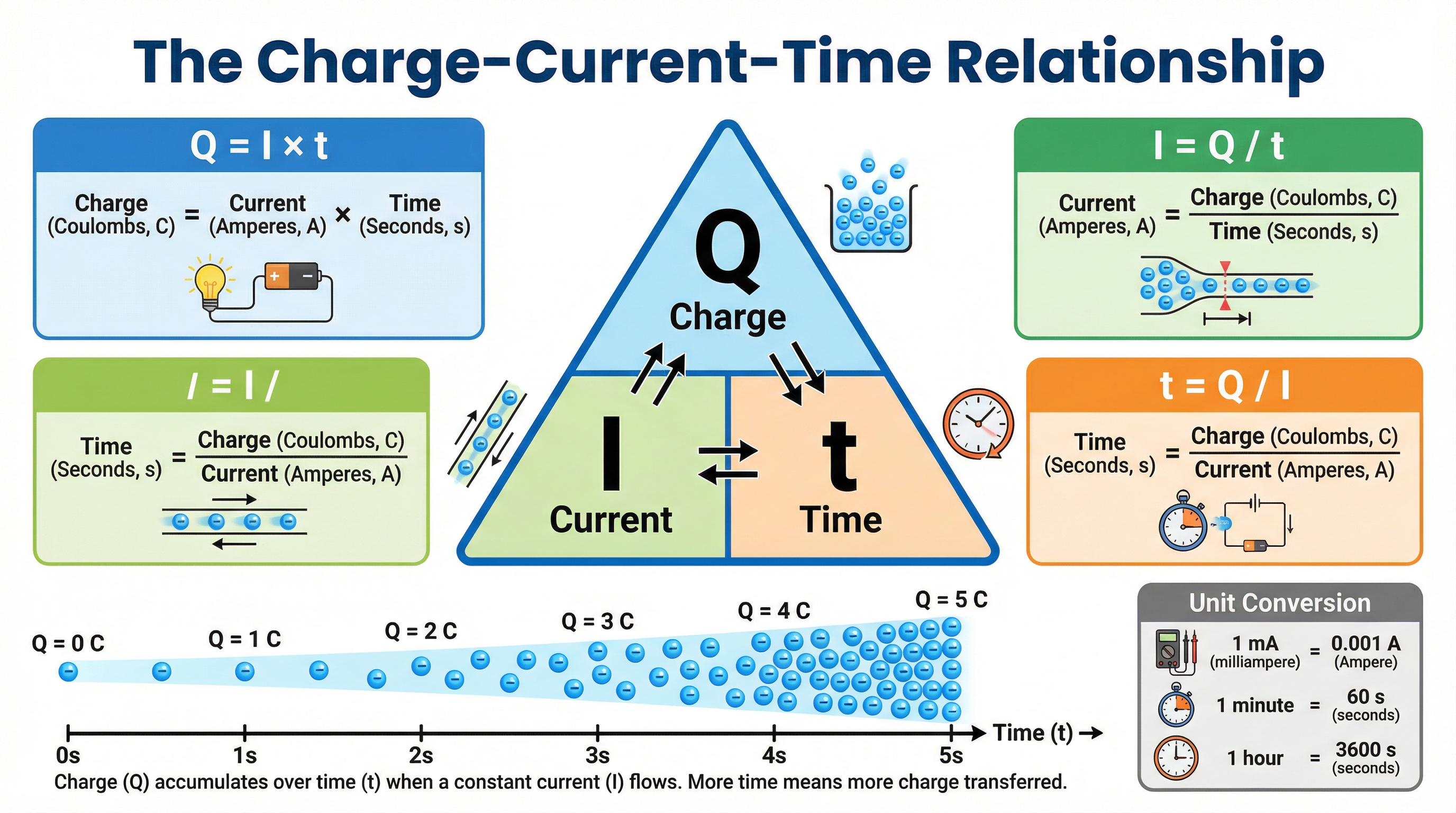
**Charge = Current × Time**
> Q = I × t
* **Q**: Charge, measured in Coulombs (C)
* **I**: Current, measured in Amperes (A)
* **t**: Time, measured in **seconds (s)**
This formula is given on the OCR Physics formula sheet, but you must be able to rearrange it to solve for current or time:
* **Current (I) = Charge (Q) / Time (t)**
* **Time (t) = Charge (Q) / Current (I)**
**Unit Conversions**: Examiners often test your ability to handle units. Remember:
* **Time**: If time is given in minutes, you MUST multiply by 60 to convert it to seconds. If in hours, multiply by 3600.
* **Current**: Often, current is given in milliamps (mA) or microamps (μA). You MUST convert these to Amps before calculating.
* 1 mA = 0.001 A (divide by 1000)
* 1 kA = 1000 A (multiply by 1000)
## Practical Applications
This topic has a required practical: using circuit diagrams to construct and check series and parallel circuits. In this practical, you would typically be asked to build a simple circuit based on a diagram, using a power pack, wires, a switch, a bulb (or resistor), and an ammeter. The key skills examiners look for are:
1. **Correctly interpreting circuit symbols.**
2. **Building the circuit as per the diagram.**
3. **Connecting the ammeter in series** to measure current.
4. **Connecting a voltmeter in parallel** to measure potential difference (Topic 3.2).
5. **Taking accurate readings** and investigating how current changes (or doesn't) in different parts of the circuit.
Examiners can test this by asking you to draw a circuit diagram, describe how to measure current, or identify errors in a diagram (e.g., an ammeter connected in parallel).