AQA · GCSE · Mathematics
Course version: 8300 · Version from Sept 2015
Mensuration and calculation: measure line segments and angles in geometric figures, including interpreting maps and scale drawings and use of bearings
Turn maps and diagrams into reliable exam marks by mastering ruler readings, angle measurement, scale conversions and three-figure bearings. This AQA GCSE guide covers both tiers, with worked solutions, active-recall practice and a ten-minute female-tutor podcast. [Download the complete JSON guide](/home/ubuntu/study_guide/aqa_gcse_mensuration_scale_bearings.json).
- 12 min read
- 4 worked examples
- 6 practice questions
- 10 key terms
Check what you remember
Read the wording for your board, then hide it and explain Line segment in your own words. Rough notes are fine. This is a self-check, with no mark or grade.
Reference: AQA
Part of a straight line bounded by two endpoints.
Study Notes
Overview
A map turns a large real place into a manageable drawing. This topic teaches you to recover the real distances and directions from that drawing, and to measure geometric figures accurately using a ruler and protractor. In the examination, a small setup error can change an otherwise straightforward answer: using the plastic edge instead of the ruler's zero, choosing the wrong protractor scale, or measuring a bearing from the destination rather than the starting point.
AQA places this content in GCSE Mathematics 8300, section 3.4.2, objective G15. It is basic Foundation content and is also assessed at Higher. The specification explicitly includes eight compass-point bearings and three-figure bearings. 1
Questions may ask candidates to measure a segment, find an angle, convert a map distance, draw a position accurately, or combine scale with direction in a multi-step journey. These skills connect directly to ratio and proportion, metric units, parallel-line angles, coordinates and triangle calculations. Your aim is not merely to obtain a number: identify the correct reference point, choose a justified method, and communicate a sensible answer. Practise retrieving the method without looking, then check your work against the solutions.
Key Concepts
1. Measuring a line segment
A line segment is the part of a straight line between two endpoints. Put the ruler's zero graduation at the first endpoint, align the ruler with the segment, and read the second endpoint from directly above. The physical edge of some rulers extends beyond zero. Starting there creates a systematic error.
If the smallest divisions are millimetres, a sensible reading is normally to the nearest millimetre, equivalent to 0.1 cm. Follow any precision specified in the question. Do not invent extra decimal places that the instrument cannot justify. A sloping segment is measured along the segment, not by its horizontal width.
If zero cannot be aligned, subtract the two readings. For endpoints at 1.3 cm and 7.7 cm, length = 7.7 − 1.3 = 6.4 cm, or 64 mm. The subtraction works because ruler readings are positions relative to a common origin; their difference is the separation.
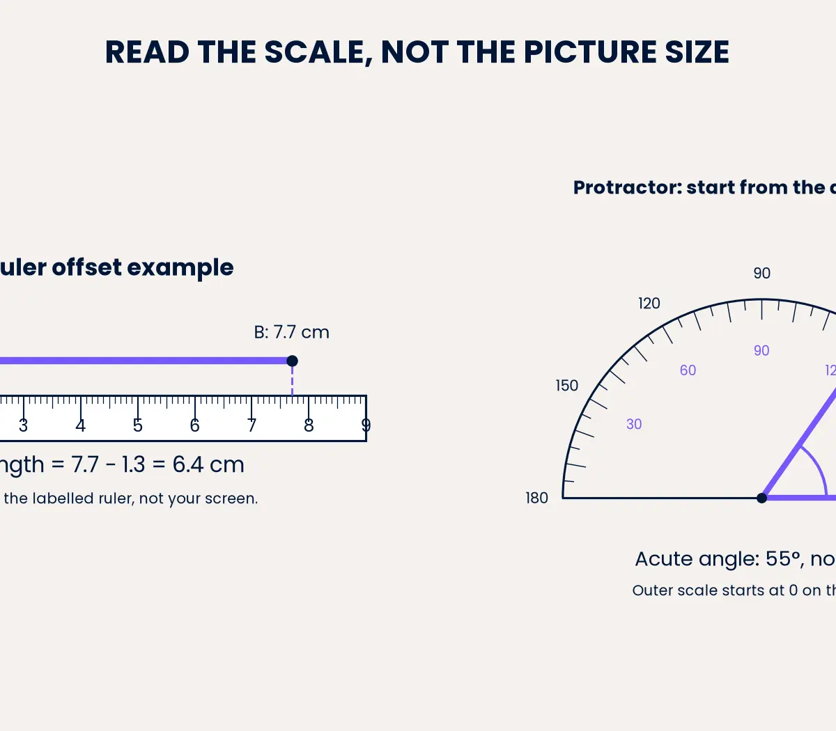
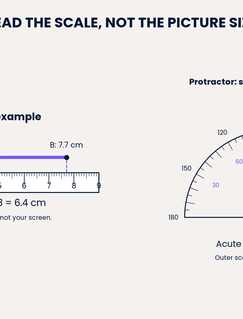
The labelled ruler above remains readable if the image is resized. Its physical size on your screen is not a calibrated centimetre scale. For paper exercises, use the intended original-size drawing or construct your own.
Cover and recall: Why is 7.7 cm not the segment's length in this example? State the calculation before checking.
2. Measuring and drawing angles
An angle measures the turn between two rays meeting at a vertex. First estimate its type: acute is below 90°, a right angle is 90°, obtuse is between 90° and 180°, and reflex is between 180° and 360°. This estimate helps reject the wrong protractor reading.
Place the protractor's centre on the vertex and its baseline along one arm. Read the scale that begins at 0° on that arm. Do not automatically choose the inner or outer scale: the correct choice depends on the orientation. In the diagram, the angle is 55°, not 125°, because the aligned arm points towards the outer scale's zero on the right.
If an arm is short, extend it with a ruler without changing its direction. To find a reflex angle, measure the smaller turn and calculate 360° minus that angle. A smaller angle of 72° corresponds to a reflex angle of 288°.
To draw a 125° angle, draw a baseline, centre the protractor on the chosen vertex, mark 125° on the appropriate scale, then join the vertex to the mark. Credit is given for the intended accurate geometry, not for a written angle label on an incorrectly drawn ray.
Why does this work? Both protractor scales describe turns from opposite starting arms. Their paired readings add to 180°.
3. Scale statements and proportional reasoning
A scale statement such as 1 cm represents 5 m means every drawing centimetre represents the same five real metres. A 4 cm line therefore represents 4 × 5 = 20 m. A real 30 m wall needs a drawing length of 30 ÷ 5 = 6 cm.
Write the scale as real units per drawing centimetre before choosing an operation. If s is that conversion value, real length = drawing length × s, while drawing length = real length ÷ s. This unit-aware method is safer than assuming all drawings are smaller than the object. A magnified drawing of a tiny component can be larger than reality.
For example, at a drawing-to-real ratio of 5:1, a 15 cm drawing represents only 3 cm in reality. Identify what each side of the ratio describes. The memory hook 'real means times; draw means divide' applies after you have expressed s as real length per drawing unit, not blindly to every printed ratio.
What if? If the scale changes from 1 cm : 5 m to 1 cm : 10 m, the same real wall occupies half as many drawing centimetres. The real wall itself has not changed.
4. Ratio scales, conversions and map data
A ratio scale 1:25 000 uses the same units on both sides. One drawing centimetre represents 25 000 real centimetres, not 25 000 metres. Since 100 cm = 1 m, that is 250 m; since 1000 m = 1 km, it is 0.25 km.
A 6.8 cm map distance represents 6.8 × 0.25 = 1.7 km. Conversely, a 4.5 km journey is 450 000 cm, so its map length is 450 000 ÷ 25 000 = 18 cm. Candidates should make the conversion visible when it is part of the method being assessed.
Remember these length conversions: 1 cm = 10 mm; 1 m = 100 cm = 1000 mm; 1 km = 1000 m = 100 000 cm. Convert once, label the result, and check its size. On a 1:50 000 map, 1 cm represents 0.5 km, so 8 cm cannot represent 400 km.
A scale bar is useful because it enlarges with the map if both are resized together. A printed ratio alone does not compensate for resizing. For a curved route, add the lengths of suitable short sections if asked for route distance; a straight line between the endpoints gives a different quantity.
For coordinate grids, inspect the axis units and increments before reading points. Here, east displacement is horizontal and north displacement is vertical. Both use kilometres at the same geometric scale. No statistical graph plotting is required by G15, but accurate coordinate reading supports its applications.
5. Bearings: north, clockwise, three figures
A bearing is a direction expressed as a clockwise angle from north at the starting point, written with three figures. Use NCT: North, Clockwise, Three figures. The bearing of B from A is measured at A towards B. Changing the reference point changes the question.
The eight compass points are N = 000°, NE = 045°, E = 090°, SE = 135°, S = 180°, SW = 225°, W = 270° and NW = 315°. Consecutive compass points differ by 45°. Use 000° for due north in normal three-figure notation. A full turn of 360° describes the same direction, but the canonical bearing range is 000° ≤ bearing < 360°.
If a route lies 37° north of east, its bearing is 90° − 37° = 053°. If a route lies 24° west of north, clockwise measurement goes almost all the way round: 360° − 24° = 336°. Do not report 024° for the second route: that points east of north.
Sketch or extend north at the specified starting point before calculating. Bearings above 180° are perfectly valid. When a semicircular protractor cannot directly read the required clockwise reflex turn, measure the smaller anticlockwise angle and subtract from 360°.
6. Reverse bearings and combined journeys
For a straight-line return journey, the reverse bearing differs by 180°, with parallel north lines. Add 180° when the original bearing is below 180°; subtract 180° otherwise. Thus 053° reverses to 233°, while 240° reverses to 060°. The subtraction prevents an answer of 420°, which lies outside the canonical range.
This follows from a half-turn reversal and parallel-line angle facts. Use the formal reasons 'corresponding angles are equal' or 'alternate angles are equal' when the marked angles support them. AQA does not accept informal labels such as 'Z angles' as mathematical reasons. 1
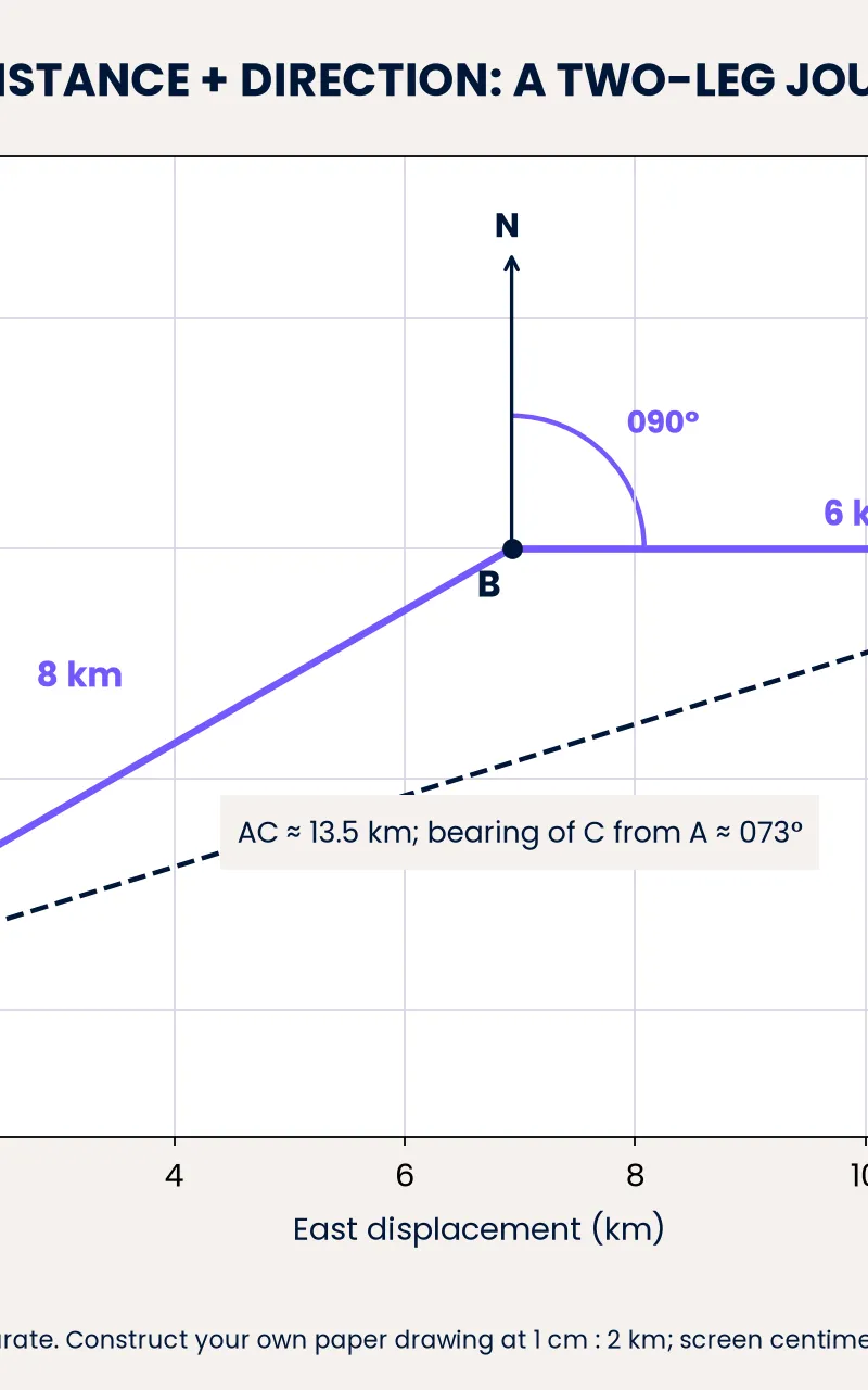
For a journey with several legs, draw each new north line at the current endpoint, parallel to the original north. At scale 1 cm : 2 km, draw 8 km on bearing 060° as a 4 cm segment, then draw 6 km due east as a 3 cm segment. Join the final endpoint to the original starting point to measure direct distance and bearing.
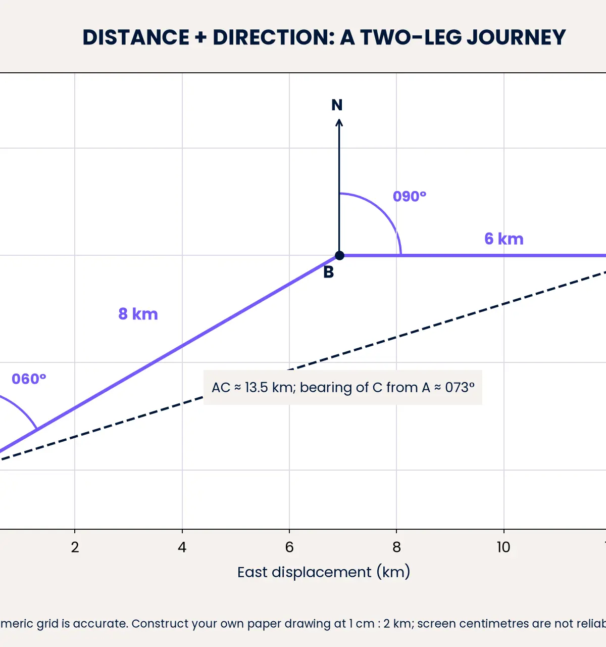
This accurate numerical diagram shows a direct distance of approximately 13.5 km and a bearing of approximately 073°. The route travelled is 8 + 6 = 14 km. Do not confuse route length with straight-line distance. Construct your own centimetre-scale paper version rather than measuring the image with a physical ruler.
Mathematical/Scientific Relationships
Core relationships: Must memorise
These relationships are not printed on the inspected AQA 2027 formula sheets. Learn their meanings and how to derive them. 3 4
Segment length = end reading − start reading, with both readings in the same unit.
For scale 1 cm : s real units, R = ds and d = R/s, where d is drawing length in centimetres, R is real length in the stated real unit, and s is real units per drawing centimetre.
For a ratio scale 1:n, R = nd and d = R/n, with R and d in identical units. The denominator n is a dimensionless scale factor.
Reverse bearing = b + 180° if b < 180°; otherwise b − 180°, where b is the outward bearing. Clockwise reflex turn = 360° − smaller anticlockwise turn.
Angles on a straight line total 180°; angles around a point total 360°; angles in a triangle total 180°. Parallel-line corresponding and alternate angles are equal; co-interior angles total 180°. These facts can turn a diagram into a calculation rather than a measurement.
Linked triangle formulas: Given on formula sheet
For 2027, both tiers receive a² + b² = c², where c is the hypotenuse of a right-angled triangle. They also receive the right-angle trigonometric relationships, equivalent to sin θ = opposite/hypotenuse, cos θ = adjacent/hypotenuse, and tan θ = opposite/adjacent. These are additional Foundation content under G20, not Higher-only. 1 3
Higher-only extension: non-right-angled bearings triangles may use a/sin A = b/sin B = c/sin C and a² = b² + c² − 2bc cos A under G22, or area = ½ab sin C under G23. All are given on the Higher 2027 sheet. Sides a, b and c lie opposite angles A, B and C. Identify the triangle's interior angle rather than substituting a bearing automatically. 1 4
Formula-sheet provision does not supply the ruler technique, the correct north line or the interpretation of a ratio. AQA confirms the 2027 sheets have the same content as those used in 2026. 5
Practical Applications
Architects use scale plans to check whether real furniture fits a room. Walkers use map scales for distance and bearings for direction. In each context, a correct direction without a correct distance is insufficient to locate a point.
There is no required science practical for this mathematics topic. A useful hands-on task is to draw your two-leg journey with a pencil, ruler and protractor, then compare your measured result with the numerical diagram. Keep construction lines visible and label points unambiguously.
Examination Use and Active Revision
All worked and practice questions in this guide are original AQA-style teaching questions. Their exact allocations are proposed practice schemes, not official AQA question-specific schemes. The authentic November 2023 8300/2F glossary distinguishes M method, A accuracy and B independent marks. Follow-through credit applies only where the scheme permits it. There is no universal measurement tolerance or automatic separate unit mark. 6
Each AQA paper has 80 marks in 90 minutes. Paper 1 is non-calculator; Papers 2 and 3 allow a calculator. Any specification area can appear on any paper. The overall budget is 1.125 minutes per mark, approximately 4.5 minutes for four marks and 6.75 minutes for six. This is pacing guidance, not an official time allocation per question. 2
When revising, cover a worked solution, attempt it, then compare the reasoning rather than just the final number. Revisit the missed step the next day and again several days later. Ask yourself why matching units matters and what would change if the scale or starting point changed.
Ten-Minute Tutor Podcast
Listen actively: 00:00 introduction; 01:00 core concepts; 06:00 exam tips and mistakes; 08:00 recall quiz; 09:00 recap and sign-off. Pause the player if you need longer to answer. The full transcript is stored in podcast_script.
References
Visual Resources
2 diagrams and illustrations
Interactive Diagrams
2 interactive diagrams to visualise key concepts
Conceptual Flow Outline
Choose the direction of a scale conversion after expressing a usable real-length-per-drawing-unit scale.
Conceptual Flow Outline
A start-point checklist and the correct piecewise rule for reversing a straight-line bearing.
Worked Examples
4 worked examples — open one to explore the question and available guidance.
Practice Questions
Try the question, then reveal an answer plan or example response
Original practice, 3 marks. A segment starts at the 2.4 cm ruler mark and ends at 9.6 cm. Calculate its length in centimetres and millimetres. Explain why the end reading alone is not its length.
Hint: Ruler readings are positions. Find the difference first.
Original practice, 3 marks. A protractor gives paired readings 68° and 112° for an indicated obtuse angle. State its value and explain your choice. Calculate the reflex angle between the same two rays.
Hint: An obtuse angle exceeds 90°. The two turns around a point total 360°.
Original practice, 4 marks. A map has scale 1:50 000. Calculate the real distance represented by 5.6 cm in kilometres. Calculate the drawing length representing 3.75 km. Show your working.
Hint: One map centimetre represents half a kilometre.
Original practice, 3 marks. Q is 28° west of north from P. Calculate the bearing of Q from P and the bearing of P from Q. Explain why the reverse direction differs by 180°.
Hint: Clockwise towards a point west of north is almost a complete turn.
Original practice, 4 marks. The bearing of B from A is 065°. The bearing of C from B is 110°. Calculate the bearing of A from B and the smaller angle ABC. BC is 6 km; calculate the length needed to draw BC at scale 1 cm : 2 km. Explain why the angle is measured at B.
Hint: First reverse AB, then compare the two directions leaving B.
Original practice, 6 marks, both tiers with linked G20 content. B is 9 km east and 12 km north of A. Calculate AB and the bearing of B from A to the nearest degree. Calculate the reverse bearing. Explain why travelling 9 km east then 12 km north is longer than travelling directly from A to B.
Hint: Draw the right-angled triangle. The bearing angle is measured from the north side, so opposite = 9 and adjacent = 12. Use degree mode.
Exam technique
How to turn what you know into marks
How to approach the question
Read the command word and identify the starting point, required quantity and units. Check whether the diagram is intended for measurement. Write a usable scale, draw the correct north line, estimate the size of the result, then carry out the measurement or calculation. Do not measure a not-accurately-drawn schematic to obtain an exact answer.
How to structure your answer
For a one-mark measurement or bearing, give the requested value with the correct unit or notation. For a 3–4-mark conversion, show the measurement or given length, scale operation, unit conversion and final answer as needed. For a 6-mark construction, leave accurate labelled segments and visible direction references, then record the requested distance and bearing. Mark totals are question-specific; do not assume one mark per written sentence. A correct answer alone normally receives full marks unless working is required, but working protects method credit if a later error occurs.
Timing
AQA papers have 90 minutes for 80 marks: 1.125 minutes, approximately 68 seconds, per mark overall. Allow roughly 3.4 minutes for 3 marks, 4.5 for 4, and 6.75 for 6, flexibly. These are planning estimates, not prescribed AQA question timings.
Common pitfalls
- Starting at the ruler edge: align the zero graduation, or subtract endpoint readings.
- Reading the wrong protractor scale: use the scale starting at zero on the aligned arm and check acute versus obtuse.
- Treating 1:25 000 as 1 cm : 25 000 m: ratio units must match.
- Using the destination north line: from A means measure at A.
- Measuring anticlockwise or omitting a leading zero: use clockwise direction and three figures.
- Reporting 420° as a reverse bearing: subtract 360°, giving 060°.
- Assuming every angle is below 180°: reflex angles and bearings above 180° are valid.
- Measuring a resized screen image as though it were printed at the original scale: use labelled scales or construct your own.
- Confusing route distance with straight-line distance: a two-leg route and the direct joining segment are different quantities.
What the command words want
- Compare
- Identify the particular numerical or geometric similarity or difference asked for; support it with values.
- Explain
- Give a mathematical reason linked to the conclusion, such as a half-turn reversal with parallel north lines.
- Measure
- Use a ruler or protractor on the intended accurately drawn figure; read to the specified or justified precision.
- Describe
- Use precise terms, such as clockwise from north or an enlargement with a specified scale factor.
- Estimate
- Give a sensible approximate value from the stated method or drawing; do not claim unsupported precision.
- Evaluate
- If used in a mathematical context, calculate the value of the expression. It does not normally mean write a general discussion of pros and cons.
- State/Give
- Provide the requested value or fact concisely, including three-figure notation for a bearing.
- Draw accurately
- Use instruments, obey scale and direction, label points and keep useful construction lines.
- Calculate/Work out
- Use the numerical information and appropriate relationships; make the scale and unit conversion clear.
- Show that/Show your working
- Write the steps that establish the requested result. Merely copying the stated result is insufficient.
Watch or listen (optional)
Test your understanding of Mensuration and calculation: measure line segments and angles in geometric figures, including interpreting maps and scale drawings and use of bearings
Active recall beats re-reading. Take an instant quiz now to test what you’ve learned and lock it into long-term memory.
7 days Premium · Then the free plan continues · No card, no charge