Pearson Edexcel · GCSE · Mathematics
Course version: 1MA1 · Version from Mar 2026
Geometry and measures - Properties and constructions: construct and interpret plans and elevations of 3D shapes
Turn a 3D solid into three accurate flat views, then use those views to recover dimensions, recognise shapes and count cubes. This GCSE guide shows candidates how to secure drawing and calculation marks without confusing perspective, footprints and volume. Download the [complete JSON study guide](/home/ubuntu/plans_elevations_guide/plans_and_elevations_study_guide.json) for all explanations, answers and the full podcast script.
- 14 min read
- 3 worked examples
- 6 practice questions
- 10 key terms
Try the lesson
The start of the Geometry and measures - Properties and constructions: construct and interpret plans and elevations of 3D shapes lesson, made from checked teaching notes for this specification point.
Have a go first
A solid cuboid is 5 cm long, 3 cm wide and 2 cm high. What shape is the plan view of this cuboid?
There is more to this lesson
The full lesson goes on to check your understanding and help you earn the marks. Create a free account to carry on, with your progress saved.
7 days Premium · Then the free plan continues · No card, no charge
Check what you remember
Read the wording for your board, then hide it and explain Plan in your own words. Rough notes are fine. This is a self-check, with no mark or grade.
Reference: Pearson Edexcel
The orthographic view of a solid from directly above.
Study Notes

Overview
A complicated-looking solid can become three manageable flat drawings. A plan shows it from directly above; a front elevation shows it from the stated front; a side elevation shows it from the stated side. Your task is not to draw an attractive picture. It is to preserve the correct dimensions and visible edges while removing the direction in which you are looking.
Pearson Edexcel GCSE Mathematics 1MA1, G13 requires candidates to construct and interpret plans and elevations of 3D shapes. This applies to both Foundation and Higher tiers. Questions can ask you to draw a view on a grid, identify a solid from its views, reconstruct a cube arrangement, or use a view to calculate a missing dimension. Pearson's teaching guidance includes two-mark drawing and reconstruction examples, but there is no fixed mark total for this topic. 1 2
These skills connect directly to scale drawings, coordinates, area and volume. The central distinction is between what a view shows and what the complete solid contains. A footprint counts occupied ground positions; an elevation records visible structure; neither automatically gives the volume. Learn the viewing direction first, then let the grid do the work.
Key Concepts
1. Orthographic views: keep it flat
Orthographic projection uses parallel lines of sight perpendicular to a viewing plane. A plan looks vertically downwards; an elevation looks horizontally across. There are no receding perspective lines and no vanishing points. A far-away part is not drawn smaller merely because it is farther from the observer.
An edge parallel to the viewing plane retains its true length, subject to the drawing scale. An edge directed straight towards the observer projects to a point. An edge angled to the plane may appear shorter. Therefore, do not measure a slanted line on a 3D illustration and assume that it is the actual length. Use given dimensions, matching parallel edges or the number of unit-cube edges.
A net is different: it unfolds a solid's surfaces. An isometric sketch is also different: it represents three dimensions using angled axes. Both can be useful representations, but neither answers a question asking for a plan or elevation.
Cover and recall: explain why a 4 cm front edge remains 4 cm in a full-size front elevation even if another edge lies farther back.
2. Decide which two dimensions survive
Stand at the front arrow before naming width and depth. Width runs left to right, depth runs front to back, and height runs vertically. The plan uses width and depth. The front elevation uses width and height. The side elevation uses depth and height. The missing dimension is flattened along your sight line.
For a cuboid 4 cm wide, 3 cm deep and 2 cm high, the plan is a 4 cm by 3 cm rectangle, the front elevation is 4 cm by 2 cm, and the side elevation is 3 cm by 2 cm. These are rectangles, not parallelograms.
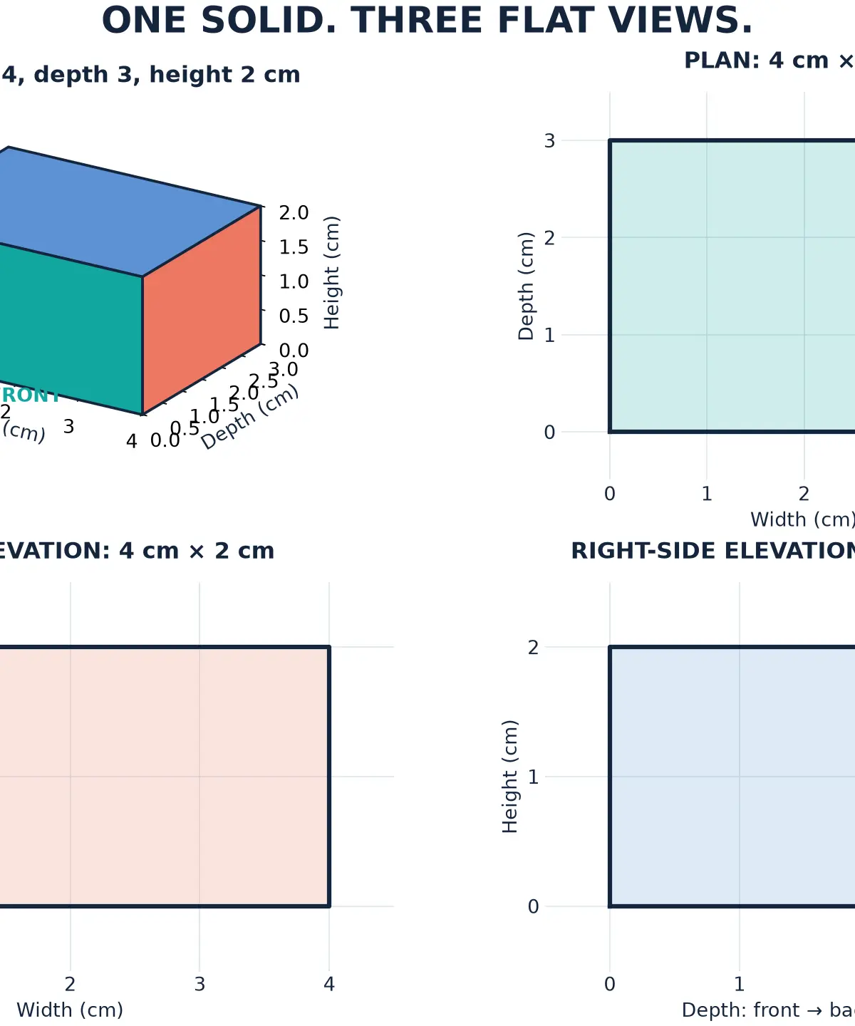
The plan and front must agree on width. The plan and side must agree on depth. Both elevations must agree on overall height. Aligning views can help you check these relationships, although a question's supplied answer spaces take priority over a particular layout convention.
This guide uses the right-side elevation, viewed from the solid's right, with front on the left of that drawing and back on the right. A left-side view can reverse that order. Follow the supplied arrow rather than assuming that every side view has the same orientation.
3. Draw a plan: occupied positions, not total cubes
For vertical cube stacks resting on a table without overhangs, the plan's footprint contains one square for each occupied ground position. A stack of three cubes still occupies one footprint square. A zero in a labelled height plan means an empty position.
Use this arrangement throughout the guide: front-row heights, left to right, are 1, 2, 1; back-row heights are 3, 0, 0. Each cube has edge length 1 cm, and each stack is filled from the table upwards. There are four occupied positions, making an L-shaped footprint: three squares across the front and one behind the leftmost square.
The total cube count is different: 1 + 2 + 1 + 3 = 7 cubes. A height label is extra information, not part of the ordinary definition of a plan. Do not add height numbers to an examination drawing unless requested or useful as clearly separate working.
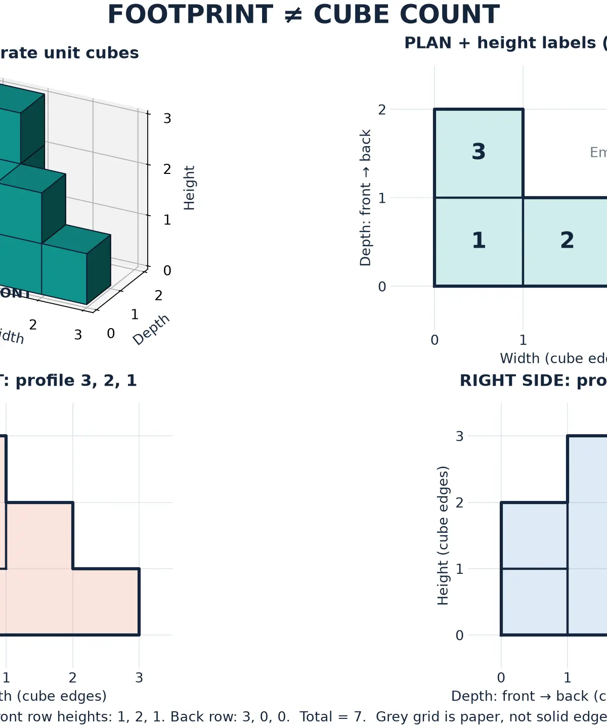
The diagram's height-labelled plan is a teaching aid. Dark lines show the outline and selected visible surface edges; the pale grid represents the paper, not extra edges of the solid.
4. Draw elevations: use the maximum, not the sum
To find the front silhouette of gap-free vertical stacks, examine each left-to-right column through the depth. Take its greatest stack height. In our example, the left column contains heights 1 and 3, so its front outline reaches 3. The middle reaches 2, and the right reaches 1. The front profile is therefore 3, 2, 1.
For the right-side silhouette, examine each front-to-back row through the width. The front row's greatest height is 2; the back row's greatest height is 3. With our orientation, the side profile is 2, 3.
Why does this work? Depth or width is collapsed, so cubes at different distances can occupy the same projected position. Adding 1 and 3 would count cubes, not draw their overlapping projection. A short front stack does not necessarily hide a taller back stack: the taller part can remain visible above it.
This maximum-height shortcut describes the silhouette of the stated gap-free stacks. For solids with holes, bridges or overhangs, inspect the actual geometry instead of forcing it into a height-table model.
5. Visible edges, steps and hidden features
Begin with the outer boundary, then inspect the visible surfaces. A change in height can create an internal line in the plan. A shorter stack in front of a taller stack can create a visible horizontal step line inside an elevation. An outline alone may therefore omit information that the question expects.
However, do not draw every known edge. An edge completely hidden behind a nearer face is not shown as a solid visible line. Hidden dashed lines are not normally required in these GCSE view drawings unless requested. For a single smooth cuboid, do not invent unit-square divisions. Where the source solid is explicitly built from separate cubes, follow the question's representation and any marking guidance on cube boundaries.
In the seven-cube example, the front-left stack has height 1 while the back-left stack has height 3. Its visible top edge appears at height 1 within the left part of the front elevation. The correct view is not simply an unbroken stepped outline.
Why question: why can a shorter stack's top edge be visible even though the elevation outline is determined by a taller stack behind it?
6. Interpret views and reconstruct solids
When three views are supplied, first identify shared dimensions. A rectangular plan and two rectangular elevations can describe a cuboid. A triangular front elevation with rectangular plan and side elevation can describe a suitably orientated triangular prism. A vertical cylinder has a circular plan and rectangular elevations. Recognising the orientation is as important as recognising the shape.
For cube arrangements, mark the occupied footprint positions. Each proposed stack must not exceed the relevant front and side outline heights, and the required maxima must actually occur. Use visible internal edges and any stated cube count as additional constraints. Check your proposed solid from all three directions before accepting it.
Do not assume three outline-only views always determine a unique cube count. Consider a fully occupied 2 by 2 footprint whose front and side profiles are both 2, 2. Front row 2, 1 and back row 1, 2 give six cubes. Making all four stacks height 2 gives eight cubes. Both have the same outline profiles and footprint. Internal surface lines could distinguish them, so this example specifically concerns outlines only.
Credit in a reconstruction task is for a solid consistent with the information actually supplied, not for guessing an invisible feature. If a unique answer is required, use all the stated constraints.
7. Accurate grid construction and scale
Read the scale before touching the ruler. If one grid square represents 2 cm, an actual width of 6 cm occupies three squares. Count the spaces between grid lines, not the number of lines. Draw lightly first, check dimensions and orientation, then make the final boundaries clear. Remove trial lines that would make your answer ambiguous.
For a scale of 1:50, each 1 cm on the drawing represents 50 cm in reality. An actual 2 m length is 200 cm, so it becomes 200 ÷ 50 = 4 cm on the drawing. Convert to consistent units before applying the ratio.
A diagram marked not accurately drawn cannot be measured for an unknown length. Given numbers and geometric relationships are the evidence. When a task says draw accurately, use the grid or stated scale; when it says sketch, preserve the correct shape and relative structure and add requested dimensions.
8. Examination evidence: marks are question-specific
The worked and practice questions below are original Edexcel-style questions with indicative teaching mark schemes, not copied Pearson questions. Their allocations show how to make a response complete, but do not replace an official question's own scheme.
For a genuine example, November 2023 Paper 3F question 19 used a cuboid's front elevation, width 8 cm and height 4 cm, together with volume 224 cm³. The required plan was a 7 cm by 8 cm rectangle. The official scheme awarded M1 for interpreting width 8 or height 4; M1 for beginning the plan with a correct side length or interpreting the elevation to find the missing depth; and C1 for the correct completed plan. 3
Summer 2022 Paper 1F question 22 linked a cylinder's plan and elevation to volume: radius 3 cm and height 5 cm gave 45π cm³, with two process marks and one accuracy mark. This illustrates why reading views accurately can support calculation as well as drawing. 4
Mathematical Relationships
No special projection formula is needed for G13. The following relationships cover the view, scale and mensuration calculations used here. Must memorise also means understand and apply; it does not mean rote learning alone. Formula-sheet labels refer to Pearson's published 2026 Foundation sheet, with shared relevant formulae at Higher tier. Check the insert for your own examination series. 5
Must memorise: dimension matching. Plan = width × depth; front = width × height; side = depth × height. These describe the axes of the views, not a claim that every view is rectangular.
Must memorise: stack projection. If h(x,y) is the number of cubes in the gap-free stack at footprint position (x,y), then front profile F(x) = max over y of h(x,y), and side profile S(y) = max over x of h(x,y). These are compact descriptions of taking the greatest height, not required examination notation. Cube count N = sum of all stack heights.
Must memorise: scale. Actual length = drawing length × n, and drawing length = actual length ÷ n, for scale 1:n and consistent units. Number of grid squares = actual length ÷ actual length represented by one square.
Must memorise: elementary mensuration. Rectangle area A = lw; right-triangle area A = bh/2; cube volume V = a³; volume of N equal cubes V = Na³; cuboid volume V = wdh. Here l, w, d, h and a are lengths, b is a triangle's base, and h in its area formula is the perpendicular height. Rearranging gives cuboid depth d = V/(wh). These specific elementary forms are not separately printed on the cited sheet.
Given on formula sheet: prism volume V = cross-sectional area × length; circle area A = πr². These support reconstruction questions involving prisms or upright cylinders. For a cylinder, V = πr²h follows from applying the given prism relationship to a circular cross-section; learn this application even though the combined cylinder expression is not separately printed.
Must memorise: unit conversions. 1 m = 100 cm; 1 cm = 10 mm; 1 m² = 10,000 cm²; 1 m³ = 1,000,000 cm³; 1 cm³ = 1,000 mm³. Area scales with the square of the length conversion, and volume with its cube. Use cm for lengths, cm² for areas and cm³ for volumes.
Practical Applications
Architects use plans for room footprints and elevations for building heights and visible surfaces. Product designers use separate views to communicate measurements without perspective distortion. In an examination context, a shed plan could supply floor dimensions while its elevation supplies height, allowing a volume or material-area calculation.
There is no required practical for this GCSE Mathematics topic. A useful optional activity needs interlocking cubes, squared paper, pencil and ruler. Build the seven-cube arrangement, look straight down for its plan, then look horizontally from the front and right. Draw each view, compare shared dimensions and check visible step lines. Keep your eye direction level rather than looking diagonally down. Rebuild from your drawings to test whether they contain enough information.
The relevant graph skills are reading a grid, interpreting its scale, counting intervals and maintaining perpendicular directions. You do not need a line of best fit or a statistical graph. A coordinate grid can precisely specify outline vertices, but connect them in boundary order rather than treating them as unrelated plotted points.
Listen, Retrieve and Apply
The ten-minute female-tutor podcast has an introduction at 0:00, core concepts at 1:00, examination advice at 6:00, quick-fire recall at 8:00 and summary at 9:00. Answer the quiz aloud before hearing the solutions. After listening, close the guide and redraw the three cuboid views. Repeat the seven-cube task tomorrow, then explain the outline-only ambiguity several days later. Use errors to choose what to practise next, rather than rereading everything indiscriminately.
Tier note: no core G13 content in this guide is Higher-only. More demanding reconstruction and synoptic problems can be appropriate on either tier; three-dimensional trigonometry is a separate Higher-tier extension, not a prerequisite for these tasks. 1 2
References
Visual Resources
2 diagrams and illustrations
Interactive Diagrams
2 interactive diagrams to visualise key concepts
Conceptual Flow Outline
Choose the correct two dimensions before constructing a plan or elevation. All node text is quoted for reliable Mermaid rendering.
Conceptual Flow Outline
Distinguish complete height information from outline constraints when reconstructing a cube arrangement.
Worked Examples
3 worked examples — open one to explore the question and available guidance.
Practice Questions
Try the question, then reveal an answer plan or example response
Original Edexcel-style practice, 3 marks, indicative allocation. STATE the view seen directly above a solid, the two dimensions shown by its front elevation, and the two dimensions shown by its side elevation.
Hint: Each view projects out one direction.
Original Edexcel-style practice, 3 marks, indicative allocation. A cuboid has actual width 6 m and depth 4 m. DRAW its plan at scale 1:100 on a grid of 1 cm squares. Each grid square is 1 cm on the drawing.
Hint: Convert metres to centimetres before applying the ratio.
Original Edexcel-style practice, 3 marks, indicative allocation. Gap-free stacks have front-row heights 2,1,3 and back-row heights 1,2,0. GIVE the front silhouette heights left to right, GIVE the right-side silhouette heights front to back, and WORK OUT the cube count. Only silhouette profiles are requested, not internal edges.
Hint: Use maxima for profiles and add all six heights for the cube count.
Original Edexcel-style practice, 4 marks, indicative allocation. A cuboid's front elevation is 8 cm wide and 3 cm high. Its volume is 120 cm³. CALCULATE its depth, then DRAW its plan on a grid where one square represents 1 cm.
Hint: Use volume = width × depth × height, then remove height from the plan.
Original Edexcel-style practice, 4 marks, indicative allocation. Only silhouettes are given. The plan is a completely occupied 2-by-2 footprint. Both front and right-side profiles are 2,2. Every stack contains one or two cubes with no gaps. FIND the minimum and maximum possible cube counts and EXPLAIN why the count is not unique.
Hint: Every row and column needs a height-2 stack, but not every stack must have height 2.
Original Edexcel-style synoptic practice, 3 marks, indicative allocation. The plan of an upright cylinder has diameter 6 cm. Its side elevation is 6 cm wide and 5 cm high. CALCULATE its volume, giving an exact answer in terms of π.
Hint: The circle-area formula uses radius, not diameter.
Exam technique
How to turn what you know into marks
How to approach the question
Find the viewing arrow and requested command. Read the grid scale. Label width, depth and height in rough working. For each requested view retain the correct two dimensions. For filled vertical stacks use occupied positions for the plan and maxima for elevation outlines. Draw the outline, add only required visible edges, then check matching dimensions. For reconstruction use every supplied view and constraint; do not assume an outline-only cube count is unique.
How to structure your answer
For DRAW, provide one clear final grid drawing, not a description. For SKETCH, show the correct 3D structure and any requested dimensions. For calculation, show the interpreted dimensions, the relationship used, substitutions and final answer with appropriate units. In this guide a 3-mark three-view task gives one indicative mark per view, a 4-mark task adds cube counting, and the 6-mark reconstruction task also credits structure, dimensions and volume. Do not transfer these allocations mechanically to official papers.
Timing
Pearson papers allow 90 minutes for 80 marks: 1.125 minutes, or 67.5 seconds, per mark as an average planning guide. Aim for about 3-4 minutes for 3 marks, 4-5 minutes for 4 marks and 6-7 minutes for 6 marks. These are revision pacing suggestions, not board-imposed timings.
Common pitfalls
- Drawing perspective: replace receding diagonals with a flat orthographic outline.
- Swapping front and side: decide from the arrow before deciding width and depth.
- Reversing side order: in this guide's right-side view, front is on the left and back on the right; other arrows can change this.
- Adding overlapping heights: use maxima for silhouettes and sums only for a complete height-plan cube count.
- Omitting visible step edges or adding hidden ones: inspect line of sight and follow the question's instructions.
- Counting grid lines instead of intervals: a 4-square length has 4 spaces, even though there are 5 bounding grid lines.
- Using footprint area as volume: a footprint loses height information.
- Measuring a not-accurately-drawn 3D sketch: use stated dimensions and mathematical relationships.
What the command words want
- Draw
- Produce the requested view using the grid and stated scale. A verbal answer is not a replacement.
- Sketch
- Show correct shape and structure; use a ruler where helpful and include dimensions when requested. A 3D sketch may use receding edges, unlike a plan or elevation.
- Compare
- Identify the particular shared or differing dimension or structure. Do not rely on vague statements such as they look different.
- Explain
- Give a mathematical reason using because, such as the back stack remains visible above the shorter front stack.
- Describe
- Specify the relevant view, dimensions or stack arrangement unambiguously; name the viewing direction.
- Evaluate
- If a claim is presented, decide whether it is valid and justify it with the views or a counterexample. Generic essay-style discussion is not normally needed for G13.
- State/Give
- Give a precise name or value, such as plan, triangular prism or 7 cubes; include units if relevant.
- Work out/Calculate
- Read the dimensions accurately, show the method when required and give a numerical answer with the correct units.
Watch or listen (optional)
Test your understanding of Geometry and measures - Properties and constructions: construct and interpret plans and elevations of 3D shapes
Active recall beats re-reading. Take an instant quiz now to test what you’ve learned and lock it into long-term memory.
7 days Premium · Then the free plan continues · No card, no charge