The Motor Effect Revision Notes
Introduction
Comprehensive revision notes for OCR GCSE.
Summary & Overview
Unlock the secrets of the Motor Effect, a cornerstone of GCSE Physics that powers everything from electric cars to your phone's vibration motor. This guide will equip you with the knowledge to master Fleming's Left-Hand Rule, deconstruct DC motors, and tackle calculation questions with confidence, securing top marks in your OCR exam.
Study Material
## Overview
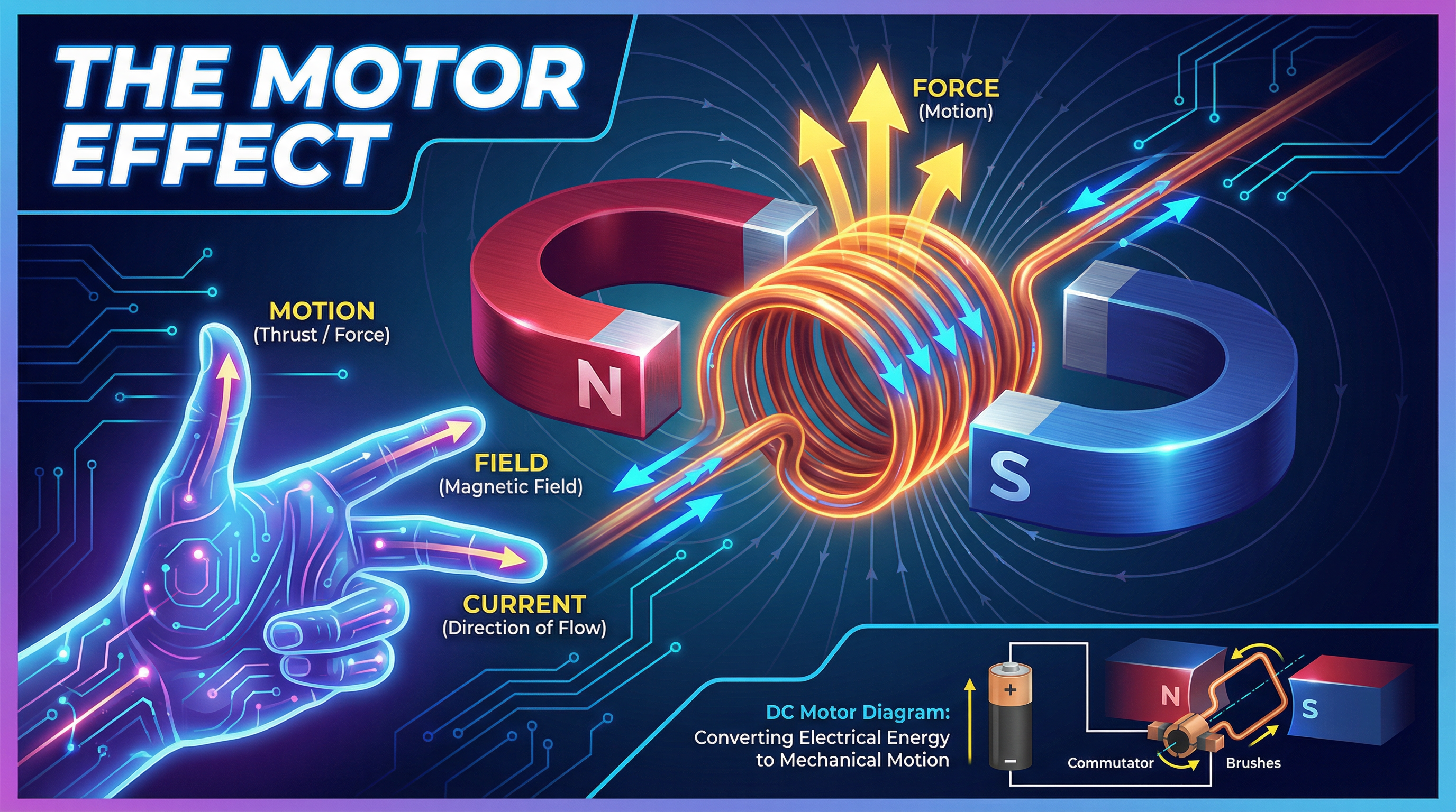
The Motor Effect is a fundamental principle in physics that describes how electrical energy is converted into mechanical motion. At its core, it is the phenomenon where a conductor carrying an electric current experiences a force when placed within a magnetic field. This effect is not just an abstract concept; it is the driving force behind countless devices we use daily, from simple fans to complex industrial machinery. For your OCR GCSE Physics exam, a thorough understanding of the Motor Effect is crucial, as it is frequently tested through a variety of question styles, including descriptive explanations, application of Fleming's Left-Hand Rule, and, for Higher Tier candidates, quantitative calculations. This topic provides a direct link between the concepts of electricity and magnetism, forming a critical part of the 'Electricity, Magnetism and Matter' section of the specification. Mastering this will not only prepare you for specific questions on motors but also deepen your understanding of electromagnetism as a whole.

## Key Concepts
### Concept 1: The Force on a Current-Carrying Conductor
The foundational principle is that a magnetic field exerts a force on a wire carrying an electric current. This happens because the current itself generates a magnetic field, which interacts with the external magnetic field it is placed in. Imagine two magnets trying to push each other apart or pull together; a similar interaction occurs between the field from the permanent magnet and the field from the wire.
To earn marks, candidates must state that the force is **perpendicular** to both the direction of the conventional current and the direction of the magnetic field lines. The size of this force can be increased in three ways:
1. **Increasing the current (I)**: A larger current creates a stronger magnetic field around the wire, leading to a greater interaction and thus a larger force.
2. **Increasing the strength of the magnetic field (B)**: A more powerful magnet provides a stronger external field (higher magnetic flux density), resulting in a greater force.
3. **Increasing the length of the wire in the field (l)**: A longer section of wire interacting with the field means more moving charges are present, so the cumulative force is larger.
### Concept 2: Fleming's Left-Hand Rule
To determine the direction of the force, we use a powerful tool: Fleming's Left-Hand Rule. It is a memory aid that relates the directions of the force, magnetic field, and current. For the exam, you must be able to apply it accurately.
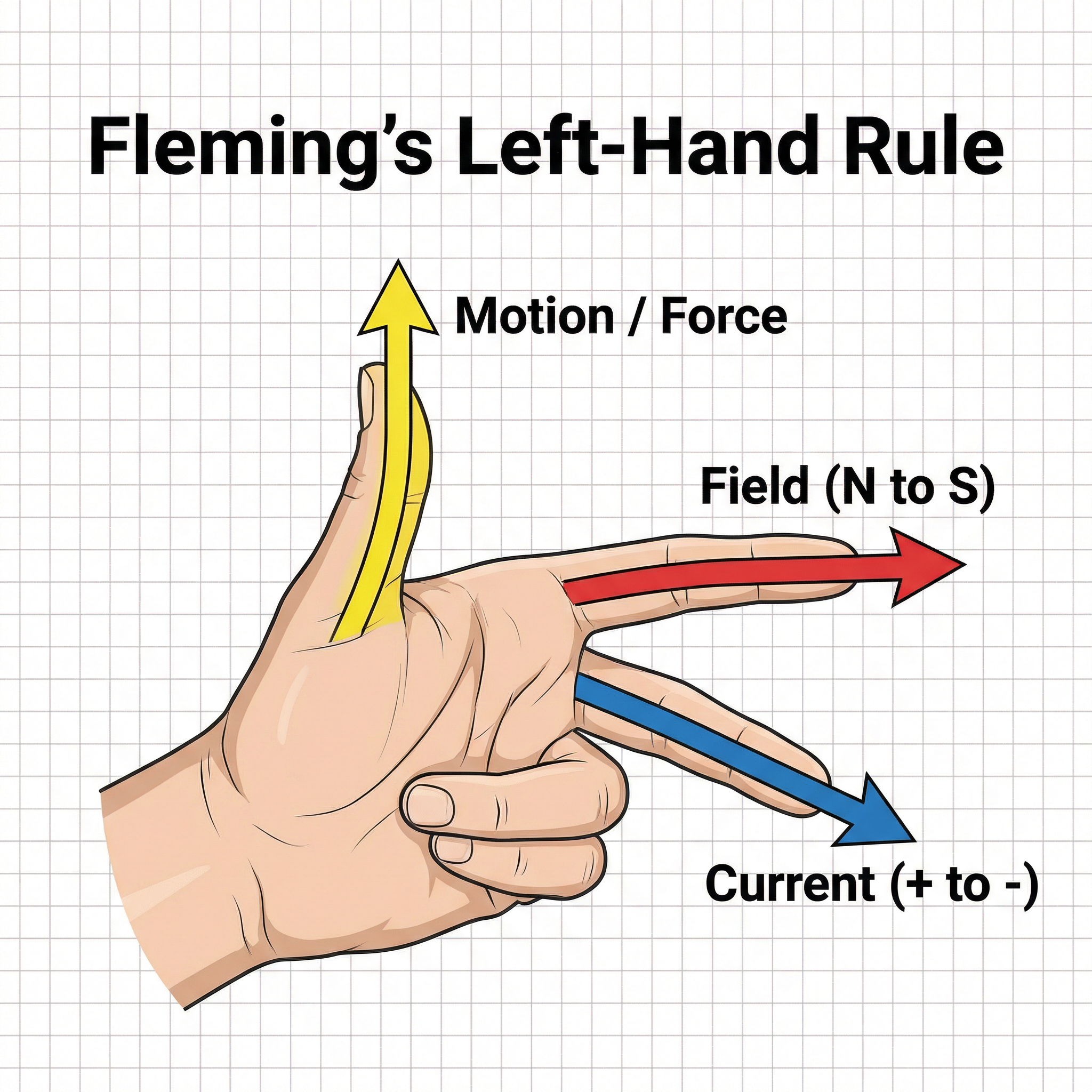
To use the rule:
- Hold your **left hand** with your thumb, first finger, and second finger all at 90 degrees to each other.
- Your **F**irst finger points in the direction of the magnetic **F**ield (from North to South).
- Your se**C**ond finger points in the direction of the conventional **C**urrent (from positive to negative).
- Your **Th**umb then points in the direction of the **Th**rust or **M**otion (the Force).
Examiners will often present diagrams with unconventional orientations. It is vital that you physically orient your hand to match the diagram on the page, rather than turning the exam paper, which can lead to errors.
### Concept 3: The DC Motor
A direct current (DC) motor is the most common application of the motor effect and a favourite for high-mark questions. It brilliantly uses the principles we've discussed to create continuous rotation.
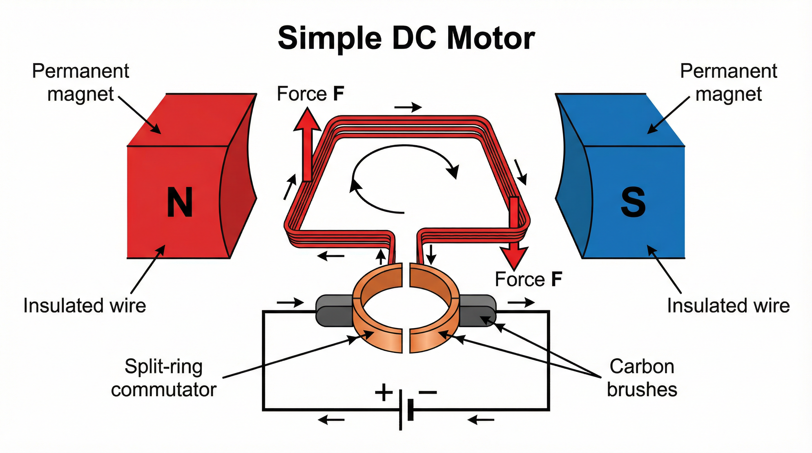
Its operation can be broken down into a sequence of events that you must be able to explain clearly:
1. **Current and Forces**: A coil of wire is placed in a magnetic field and connected to a DC power supply. Current flows into one side of the coil and out of the other.
2. **Rotation**: Using Fleming's Left-Hand Rule, we find that the force on one side of the coil is upwards, while the force on the other side is downwards. This pair of forces creates a turning effect (a torque), causing the coil to rotate.
3. **The Split-Ring Commutator**: This is the crucial component that ensures continuous rotation. It is a metal ring split into two halves, connected to the ends of the coil. As the coil rotates, the commutator spins with it.
4. **Reversing the Current**: Every half turn (when the coil is in the vertical position), the gaps in the commutator pass over the stationary carbon brushes. This action reverses the direction of the current flowing into the coil. By reversing the current just as the forces are about to switch direction, the forces on each side of the coil are also reversed, ensuring the turning effect continues to push the coil in the **same direction**.
5. **Momentum**: When the coil is vertical, the forces are pulling it apart rather than causing rotation, and the commutator momentarily disconnects the current. The coil's momentum carries it past this vertical point, allowing the commutator to reconnect and the cycle to continue.
### Concept 4: The Motor Equation (Higher Tier Only)
For Higher Tier candidates, the relationship between force, magnetic field strength, current, and length is quantified by the following equation:
## Mathematical/Scientific Relationships
**Force = Magnetic Flux Density × Current × Length**
`F = BIl`
- **F**: Force, measured in Newtons (N)
- **B**: Magnetic Flux Density (a measure of the magnetic field's strength), measured in Tesla (T)
- **I**: Current, measured in Amperes (A)
- **l**: Length of the conductor within the magnetic field, measured in metres (m)
This formula is **Given on the formula sheet**. However, you must be able to rearrange it to solve for B, I, or l. For example, to find the magnetic flux density, the formula becomes `B = F / (Il)`.
**Crucial Unit Conversion**: Examiners frequently provide the length in centimetres (cm). You **must** convert this to metres (m) before substituting it into the equation. To convert from cm to m, divide by 100. Failure to do so is a very common mistake that results in losing a mark.
## Practical Applications
The motor effect is ubiquitous in modern technology. Understanding its principles allows you to see the physics at work all around you:
- **Electric Vehicles**: Large electric motors, operating on these principles, turn the wheels.
- **Home Appliances**: Blenders, washing machines, hairdryers, and fans all rely on electric motors to function.
- **Loudspeakers**: A loudspeaker works like a motor in reverse and forwards. An alternating current in a coil attached to a cone moves it back and forth within a magnetic field, creating sound waves.
- **Hard Disk Drives**: Tiny motors spin the magnetic platters at thousands of revolutions per minute, allowing data to be read and written.


