Pearson Edexcel · A-Level · Computer Science
Boolean Algebra
Master the core of digital logic with this guide to Boolean Algebra for Edexcel A-Level Computer Science. We break down complex simplification, Karnaugh maps, and logic circuits into exam-focused, easy-to-revise chunks, helping you secure top marks.
- 7 min read
- 3 worked examples
- 5 practice questions
- 6 key terms
Check what you remember
Read the wording for your board, then hide it and explain Boolean Algebra in your own words. Rough notes are fine. This is a self-check, with no mark or grade.
Reference: Pearson Edexcel
A branch of algebra in which the variables' values are the truth values true (1) and false (0), and the primary operations are the logical operations AND, OR, and NOT.
Study Notes
Overview
Boolean Algebra is the mathematics of digital systems, providing a formal way to reason about logical states (true/false, 1/0). For an A-Level Computer Science candidate, it is not just abstract theory; it is the fundamental language spoken by the hardware you program. It underpins everything from CPU design and circuit analysis to database query logic. Examiners frequently test this topic (7.1) because it assesses pure analytical skill (AO2) and the ability to apply formal methods to solve complex problems (AO3). A typical exam question will require you to take a complex, un-optimised Boolean expression and simplify it using algebraic laws or a Karnaugh map, and then draw the resulting logic circuit. Mastering this topic demonstrates a deep understanding of how computation actually happens at the hardware level.
Key Concepts
Concept 1: Logic Gates & Truth Tables
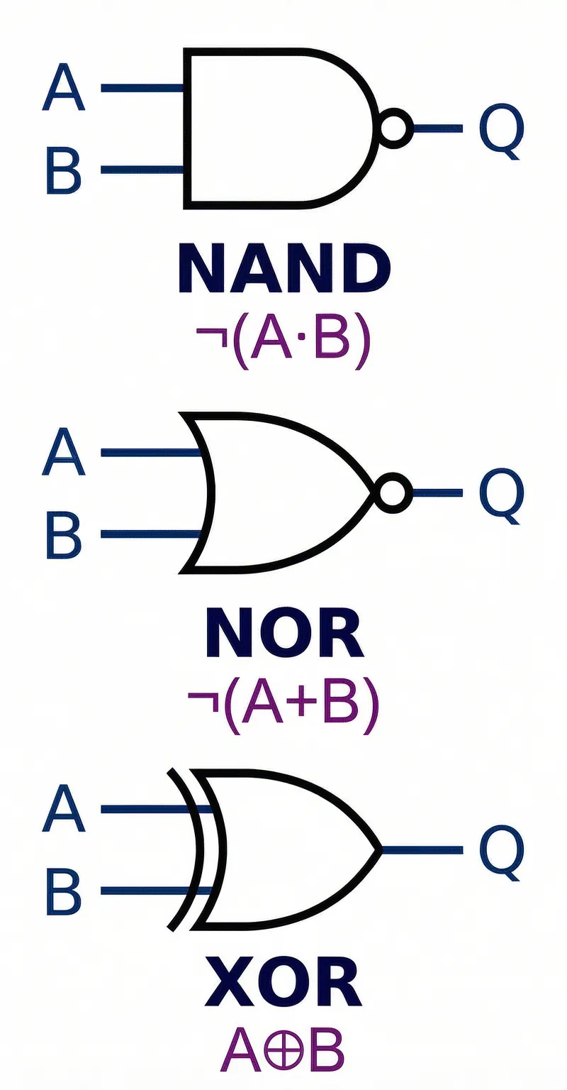
Logic gates are the basic building blocks of digital circuits. Each gate implements a specific Boolean function. To earn marks, you must be able to recall the symbol, the Boolean expression, and the truth table for the seven key gates.
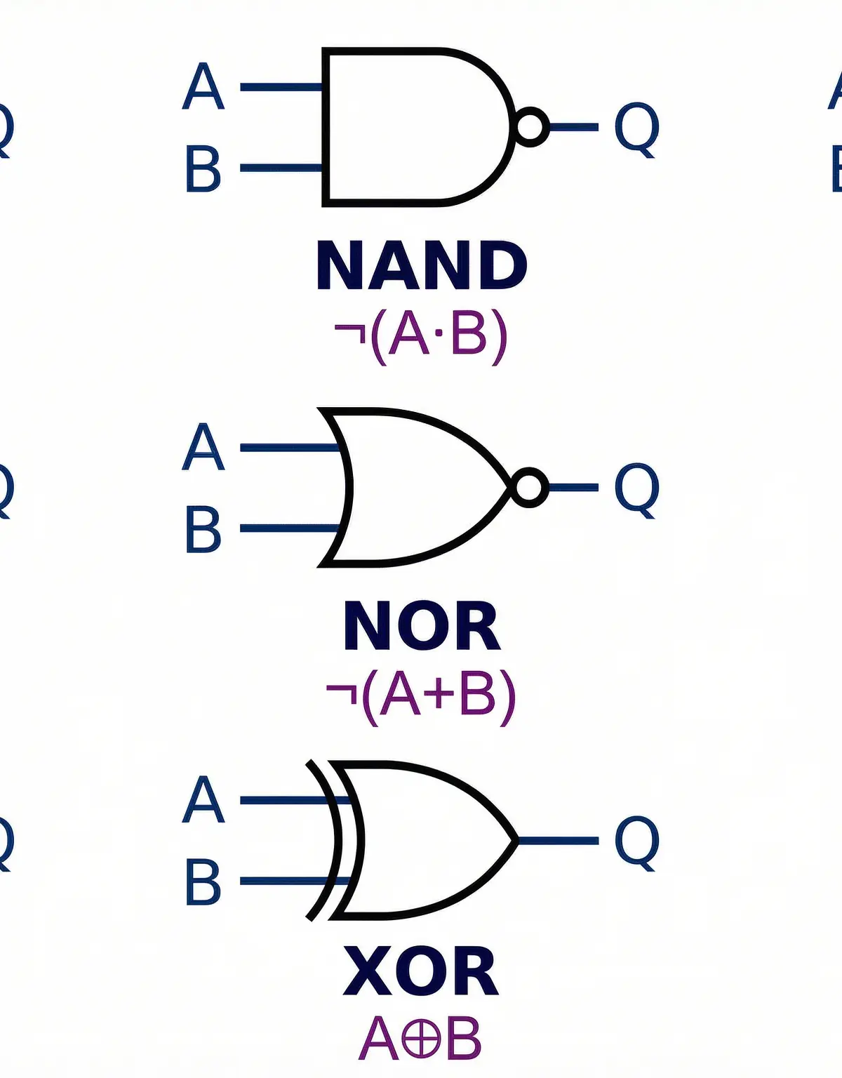
- AND (·): Output is 1 only if all inputs are 1. (Think: A and B must be true).
- OR (+): Output is 1 if at least one input is 1. (Think: A or B can be true).
- NOT (¬ or bar): Inverts the input. A 1 becomes a 0, and a 0 becomes a 1.
- NAND: The opposite of AND. Output is 0 only if all inputs are 1.
- NOR: The opposite of OR. Output is 1 only if all inputs are 0.
- XOR (⊕): Exclusive OR. Output is 1 only if the inputs are different.
- XNOR: The opposite of XOR. Output is 1 only if the inputs are the same.
Universal Gates: NAND and NOR are known as universal gates because any other logic gate can be constructed using only NAND gates or only NOR gates. For example, a NOT gate can be made by connecting both inputs of a NAND gate together.
Concept 2: Boolean Laws for Simplification
Boolean laws are rules that allow you to manipulate and simplify expressions. Writing the name of the law you are using next to each step of your working is crucial for securing method marks.
Key Laws to Memorise:
| Law Name | AND Form | OR Form | Explanation |
|---|---|---|---|
| Identity | A · 1 = A | A + 0 = A | ANDing with 1 or ORing with 0 doesn't change the value. |
| Null/Annihilation | A · 0 = 0 | A + 1 = 1 | ANDing with 0 always gives 0; ORing with 1 always gives 1. |
| Idempotent | A · A = A | A + A = A | A variable combined with itself is just itself. |
| Complement | A · ¬A = 0 | A + ¬A = 1 | A variable and its inverse are mutually exclusive. |
| Commutative | A · B = B · A | A + B = B + A | The order of inputs doesn't matter. |
| Associative | (A·B)·C = A·(B·C) | (A+B)+C = A+(B+C) | Grouping of inputs doesn't matter for the same operator. |
| Distributive | A·(B+C) = A·B+A·C | A+(B·C) = (A+B)·(A+C) | You can expand brackets, similar to regular algebra. |
| Absorption | A + (A·B) = A | A · (A+B) = A | A more complex term is 'absorbed' by a simpler one. |
| Double Negation | ¬(¬A) = A | Two NOTs cancel each other out. |
Concept 3: De Morgan's Laws
De Morgan's Laws are critical for simplification, especially when dealing with negated groups of variables. They are tested in almost every paper.
- Law 1: ¬(A · B) ≡ ¬A + ¬B
- Law 2: ¬(A + B) ≡ ¬A · ¬B
The key is to remember the phrase: 'Break the bar, change the operator.' When you split a NOT bar that covers multiple terms, you must flip the operator from AND to OR, or from OR to AND.
Concept 4: Karnaugh Maps (K-maps)
Karnaugh maps are a graphical method for simplifying Boolean expressions for up to 4 variables. They provide a visual way to spot redundant terms that is often faster and less error-prone than pure algebra.
Steps for using a K-map:
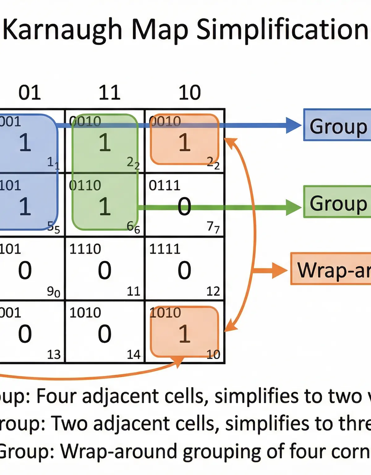
- Draw the Grid: Create a grid with rows and columns labelled using Gray Code (00, 01, 11, 10). This is vital, as it ensures adjacent cells only differ by one bit.
- Populate the Map: Place a '1' in each cell corresponding to a term in your sum-of-products expression.
- Group the 1s: Draw loops around rectangular groups of 1s. The rules are:
- Groups must contain a number of cells that is a power of 2 (1, 2, 4, 8).
- Groups must be as large as possible.
- You must create the fewest number of groups possible to cover all the 1s.
- Groups can wrap around from the top row to the bottom, and the left column to the right.
- Read the Expression: For each group, identify the variable(s) that do not change. These form the simplified term. OR all the terms together for the final expression.
Concept 5: Adders & D-type Flip-Flops
These are fundamental combinational and sequential logic circuits you must know.
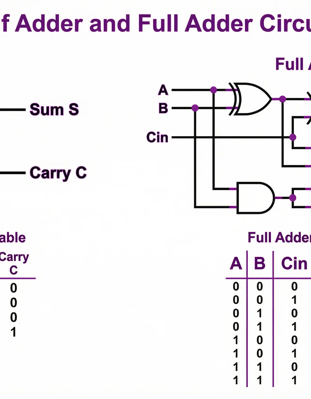
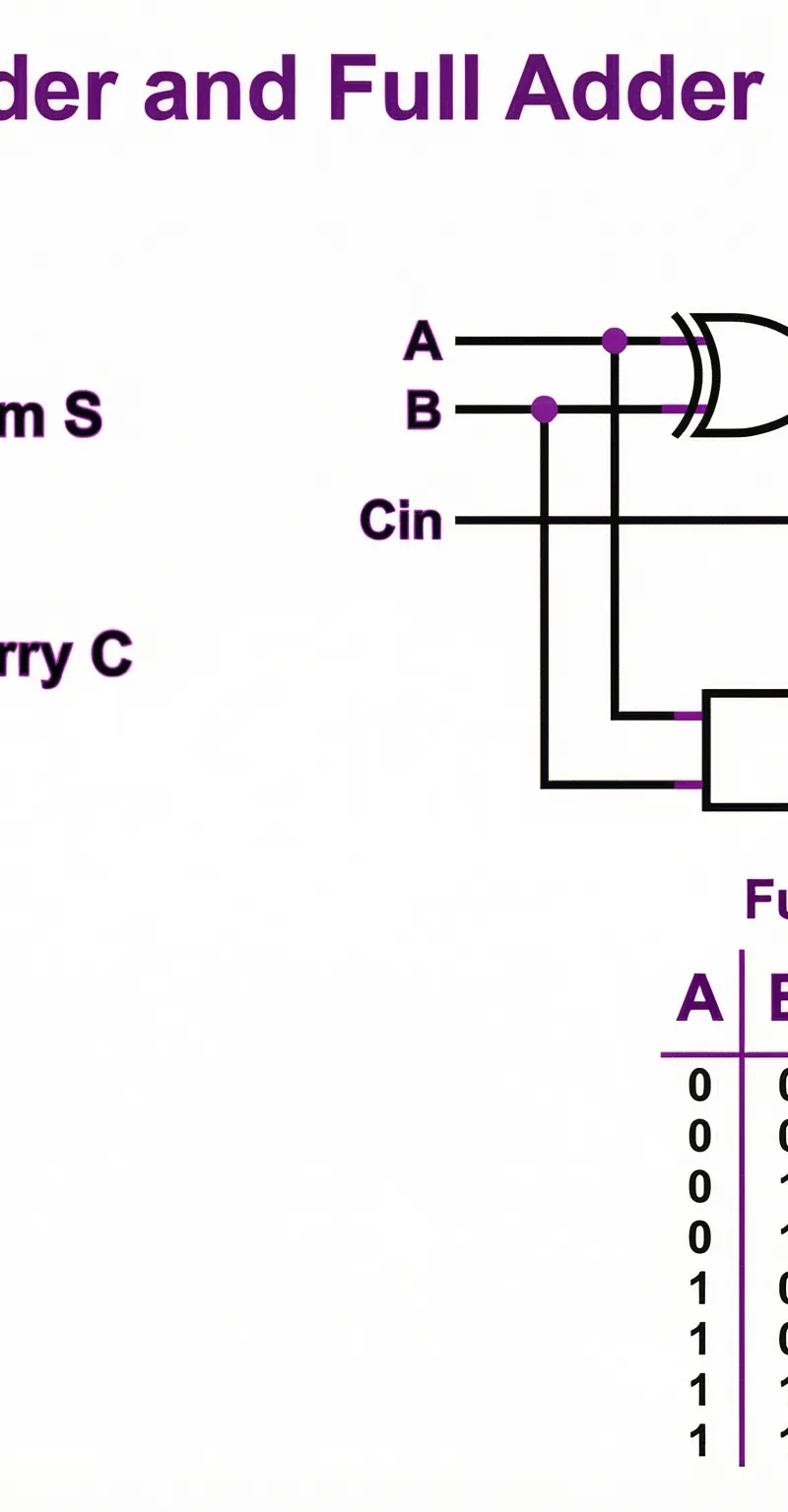
- Half Adder: Adds two single bits (A, B) and produces a Sum (A ⊕ B) and a Carry (A · B). It cannot handle a carry-in from a previous addition.
- Full Adder: Adds three single bits (A, B, Cin) and produces a Sum and a Carry Out. Full adders can be chained together (cascaded) to create ripple-carry adders for multi-bit numbers.
- D-type Flip-Flop: A sequential logic circuit that stores one bit of data. It has a Data input (D), a Clock input (CLK), and an output (Q). On the rising edge of the clock pulse, the output Q takes on the current value of the input D. This is the fundamental building block of computer memory (registers). Its behaviour is described by the characteristic equation: Q(t+1) = D.
Mathematical/Scientific Relationships
- Sum of Products (SOP): An expression formed by ORing together multiple AND terms (e.g., (A·B) + (¬A·C)). This is the most common form derived from truth tables and K-maps.
- Product of Sums (POS): An expression formed by ANDing together multiple OR terms (e.g., (A+B) · (¬A+C)).
Practical Applications
- CPU Design: The Arithmetic Logic Unit (ALU) at the heart of a CPU is built from logic gates, using circuits like adders to perform calculations.
- Memory: D-type flip-flops are used to construct Static RAM (SRAM), which serves as fast cache memory in a CPU.
- Control Systems: Logic gates are used in embedded systems to control machinery based on sensor inputs (e.g., a security system that triggers an alarm if a door sensor AND a motion sensor are activated).
- Database Queries: The SQL
WHEREclause uses Boolean operators (AND, OR, NOT) to filter data, applying the exact same logical principles.
Visual Resources
3 diagrams and illustrations

Interactive Diagrams
2 interactive diagrams to visualise key concepts
Conceptual Flow Outline
Flowchart showing the process of Boolean simplification from expression to final circuit diagram.
Conceptual Flow Outline
Concept map illustrating the component gates of a Half Adder versus a Full Adder.
Worked Examples
3 worked examples — open one to explore the question and available guidance.
Practice Questions
Try the question, then reveal an answer plan or example response
Draw a logic gate circuit to represent the un-simplified Boolean expression F = ¬(A + B) + (A · B).
Hint: Build the circuit piece by piece. Start with the inputs A and B, then the gates inside the brackets.
Simplify the expression Q = (X + Y) · (¬X + Y) using Boolean algebra.
Hint: Use the distributive law first, then look for terms that can be eliminated.
A system has three inputs, A, B, and C. The output Z is 1 only if a majority of the inputs are 1. Derive the simplified sum-of-products expression for Z using a Karnaugh map.
Hint: First, write out the truth table to identify the rows where the output is 1. A majority means 2 or 3 inputs are 1.
Construct a NOT gate, an AND gate, and an OR gate using only two-input NAND gates.
Hint: Remember that NAND is a universal gate. For NOT, think about what happens if you feed the same signal to both inputs of a NAND gate.
Explain the purpose of the Gray code ordering in a Karnaugh map.
Hint: Think about what defines an adjacent group of cells.
Exam technique
How to turn what you know into marks
How to approach the question
1. Identify the command word (Simplify, Draw, Derive). 2. Choose your method: algebra or K-map. K-maps are usually better for 3-4 variables. 3. Show every single step of your working. 4. Write the name of the law used at each algebraic step. 5. Double-check your answer by substituting test values.
How to structure your answer
For simplification: present a step-by-step derivation. For circuit diagrams: use a ruler, use standard gate symbols, and label all inputs and outputs clearly.
Timing
Approximately 1 minute per mark. A 4-mark simplification question should be completed in under 5 minutes.
Common pitfalls
- Failing to change the operator when applying De Morgan's Laws.
- Creating non-power-of-two groups in K-maps (e.g., groups of 3 or 6).
- Forgetting to check for wrap-around groups in K-maps.
- Omitting method steps in algebraic simplification, losing method marks.
What the command words want
- Compare
- Give similarities AND differences. E.g., 'Compare a half adder and a full adder.'
- Explain
- Provide reasons, using 'because'. E.g., 'Explain why a NAND gate is considered universal.' -> 'Because any other logic gate can be constructed from a combination of NAND gates.'
- Describe
- Provide the key characteristics. E.g., 'Describe the function of a D-type flip-flop.'
- Evaluate
- Not common for this topic, but would require a judgement based on criteria (e.g., efficiency, cost).
- State/Give
- A short, factual answer. E.g., 'State the expression for a half-adder's sum output.' -> 'A ⊕ B'.
- Calculate/Simplify
- Show all intermediate steps of your working to guarantee method marks.
Watch or listen (optional)
Test your understanding of Boolean Algebra
Active recall beats re-reading. Take an instant quiz now to test what you’ve learned and lock it into long-term memory.
7 days Premium · Then the free plan continues · No card, no charge