Boolean Algebra Revision Notes

    Subject: Computer Science | Level: GCSE | Exam Board: OCR

    Master Boolean Algebra for your OCR GCSE Computer Science exam. This guide breaks down logic gates, truth tables, and circuit diagrams into easy-to-understand concepts, packed with examiner tips and interactive content to help you secure top marks in Component 02."

    Revision Notes & Key Concepts

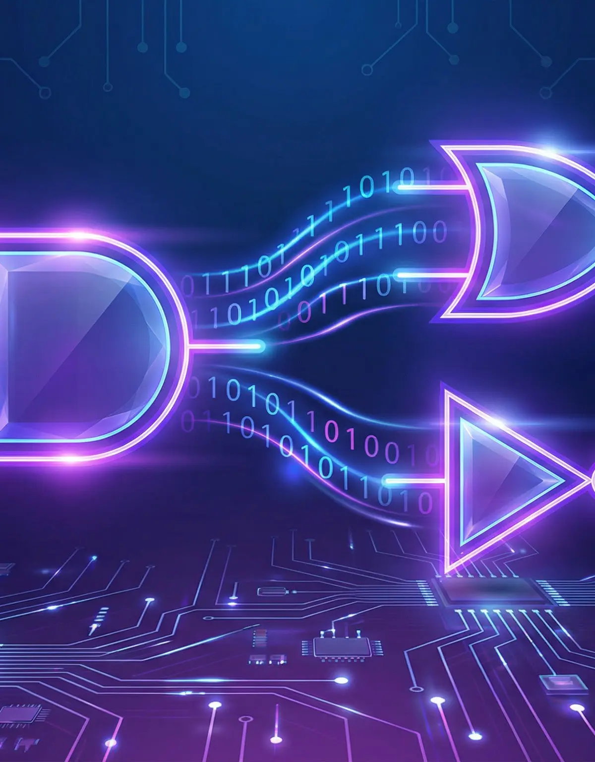
    ![header_image.png](https://xnnrgnazirrqvdgfhvou.supabase.co/storage/v1/object/public/study-guide-assets/guide_bc4ffc6e-b38a-43cf-9b6b-5bdcef1a4161/header_image.png) ## Overview Boolean Algebra is the mathematics of logic, and it forms the bedrock of all digital computing. For your OCR GCSE (J277), this topic (7.1) is all about how computers make decisions using simple TRUE or FALSE values, represented by binary 1s and 0s. Understanding this is not just about passing the exam; it’s about grasping the fundamental principles that make processors, memory, and all digital hardware function. In Component 02, you won't just be asked to define terms; you'll be expected to apply your knowledge by drawing logic circuits, completing complex truth tables, and writing logical expressions. This is a heavily practical topic where showing your working and being precise with your diagrams is key to earning the majority of marks, which are weighted towards AO2 (application). ![boolean_algebra_podcast.mp3](https://xnnrgnazirrqvdgfhvou.supabase.co/storage/v1/object/public/study-guide-assets/guide_bc4ffc6e-b38a-43cf-9b6b-5bdcef1a4161/boolean_algebra_podcast.mp3) ## Key Concepts ### Concept 1: The Three Fundamental Logic Gates At the heart of Boolean logic are three essential gates that perform the basic logical operations: AND, OR, and NOT. Every complex logical operation a computer performs can be broken down into combinations of these three gates. **AND Gate**: Think of this as a strict bouncer at a club who will only let you in if you have **both** your ID and your ticket. The output is 1 (TRUE) only if **all** inputs are 1. If any input is 0 (FALSE), the output is 0. - **Symbol**: A distinctive D-shape with a flat back. - **Boolean Expression**: `Q = A AND B` or `Q = A · B` **OR Gate**: This gate is more relaxed. The output is 1 if **at least one** of the inputs is 1. It only outputs 0 if all inputs are 0. Think of it like needing either a bus pass OR a train ticket to use public transport. - **Symbol**: A shield-like shape with a curved back. - **Boolean Expression**: `Q = A OR B` or `Q = A + B` **NOT Gate (Inverter)**: The simplest of all. It has only one input and one output, and its job is to flip the input value. If the input is 1, the output is 0. If the input is 0, the output is 1. - **Symbol**: A triangle with a small circle (the 'inverter bubble') at its point. - **Boolean Expression**: `Q = NOT A` or `Q = Ā` ![logic_gates_symbols.png](https://xnnrgnazirrqvdgfhvou.supabase.co/storage/v1/object/public/study-guide-assets/guide_bc4ffc6e-b38a-43cf-9b6b-5bdcef1a4161/logic_gates_symbols.png) ### Concept 2: Truth Tables A truth table is a mathematical table used in logic to compute the functional values of logical expressions on each of their functional arguments. In simpler terms, it’s a way of systematically listing every possible input combination for a logic circuit and showing what the output will be for each one. For a circuit with 'n' inputs, there will be 2^n possible combinations. For the GCSE, you will typically deal with 2 or 3 inputs, resulting in 4 or 8 rows in your truth table. **Example**: A 2-input AND gate truth table. | A | B | Q (A AND B) | |---|---|-------------| | 0 | 0 | 0 | | 0 | 1 | 0 | | 1 | 0 | 0 | | 1 | 1 | 1 | Examiners award marks for each correctly completed output row, so accuracy is vital. Always follow the standard binary counting pattern (00, 01, 10, 11) to ensure you don't miss any combinations. ![truth_table_example.png](https://xnnrgnazirrqvdgfhvou.supabase.co/storage/v1/object/public/study-guide-assets/guide_bc4ffc6e-b38a-43cf-9b6b-5bdcef1a4161/truth_table_example.png) ### Concept 3: Combining Gates & Logic Circuits The real power of Boolean logic comes from combining these simple gates to create complex circuits that can perform useful functions. OCR exams will require you to analyse circuits with multiple gates and determine the final output for a given set of inputs. **Order of Precedence**: When evaluating a complex logical expression, there is a set order of operations, just like BIDMAS in maths. 1. **NOT** (operations inside brackets are always done first) 2. **AND** 3. **OR** For example, in the expression `Q = (A OR B) AND NOT C`, you would first evaluate `A OR B` and `NOT C` separately, and then you would AND the results together. Using brackets is essential to avoid ambiguity and ensure you follow the logic intended by the circuit diagram. ![logic_circuit_example.png](https://xnnrgnazirrqvdgfhvou.supabase.co/storage/v1/object/public/study-guide-assets/guide_bc4ffc6e-b38a-43cf-9b6b-5bdcef1a4161/logic_circuit_example.png) ## Mathematical/Scientific Relationships Boolean algebra has its own set of mathematical laws that can be used to simplify complex expressions. While you don't need to memorise all of these for GCSE, understanding the concepts is useful. - **Commutative Law**: `A AND B` is the same as `B AND A`. `A OR B` is the same as `B OR A`. - **Associative Law**: `(A AND B) AND C` is the same as `A AND (B AND C)`. - **Distributive Law**: `A AND (B OR C)` is the same as `(A AND B) OR (A AND C)`. These relationships are the foundation of how circuit designers can simplify complex hardware, making it cheaper and more efficient. ## Practical Applications Every single decision made by a computer is an application of Boolean logic. Here are a few examples: - **CPU (Central Processing Unit)**: The Arithmetic Logic Unit (ALU) within the CPU uses complex logic circuits to perform calculations like addition, subtraction, and comparison. - **Memory (RAM)**: Logic gates are used to create flip-flop circuits, which can store a single bit of information (a 1 or a 0). Millions of these together form your computer's memory. - **Search Engines**: When you search for `"cats" AND "dogs"`, the search engine is using a logical AND operation to find pages containing both terms."

    Worked Examples

    Practice Questions

    Boolean Algebra

    Master Boolean Algebra for your OCR GCSE Computer Science exam. This guide breaks down logic gates, truth tables, and circuit diagrams into easy-to-understand concepts, packed with examiner tips and interactive content to help you secure top marks in Component 02."

    5
    Min Read
    3
    Examples
    5
    Questions
    0
    Key Terms
    🎙 Podcast Episode
    Boolean Algebra
    0:00-0:00

    Study Notes

    header_image.png

    Overview

    Boolean Algebra is the mathematics of logic, and it forms the bedrock of all digital computing. For your OCR GCSE (J277), this topic (7.1) is all about how computers make decisions using simple TRUE or FALSE values, represented by binary 1s and 0s. Understanding this is not just about passing the exam; it’s about grasping the fundamental principles that make processors, memory, and all digital hardware function. In Component 02, you won't just be asked to define terms; you'll be expected to apply your knowledge by drawing logic circuits, completing complex truth tables, and writing logical expressions. This is a heavily practical topic where showing your working and being precise with your diagrams is key to earning the majority of marks, which are weighted towards AO2 (application).

    boolean_algebra_podcast.mp3

    Key Concepts

    Concept 1: The Three Fundamental Logic Gates

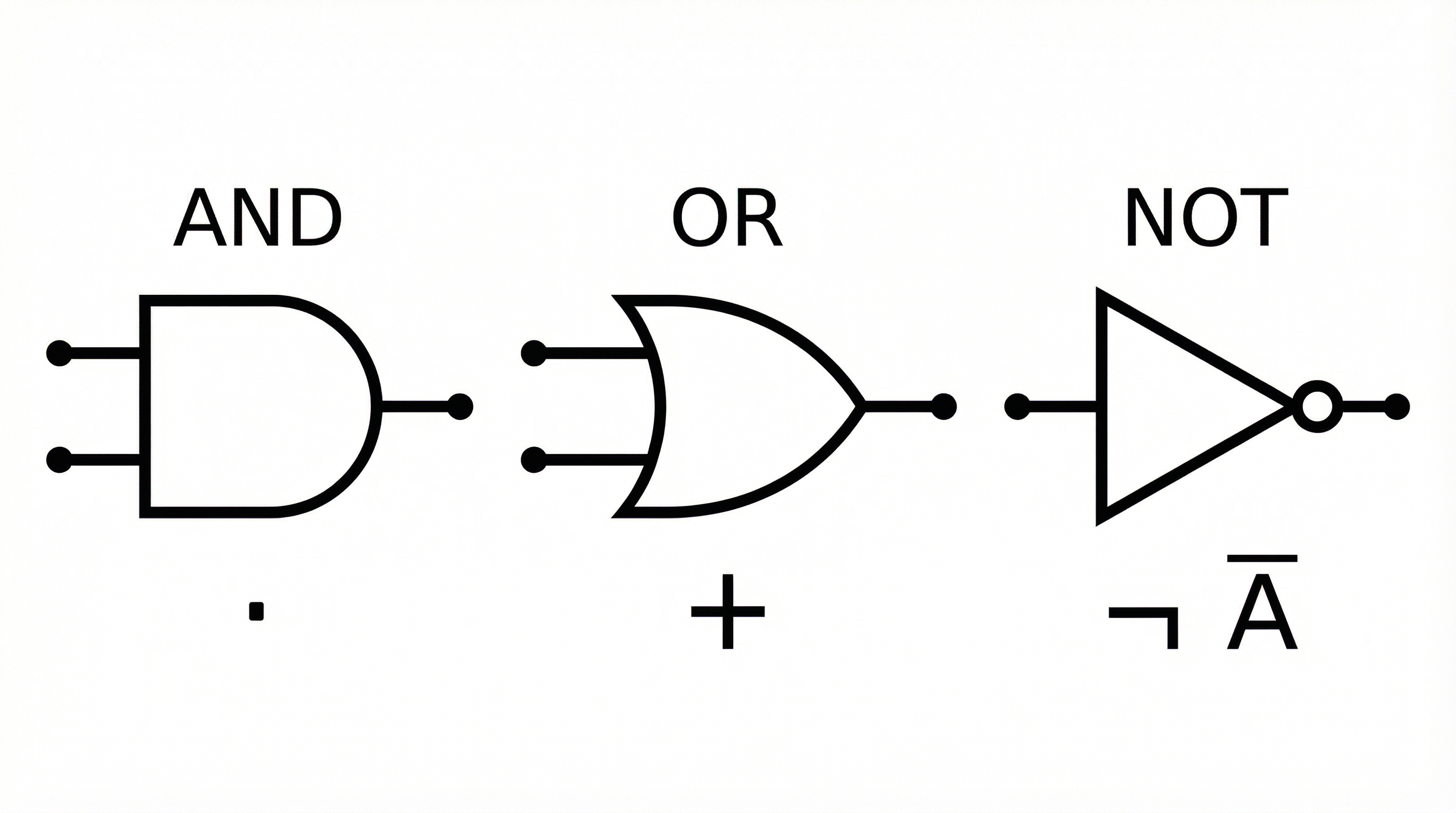
    At the heart of Boolean logic are three essential gates that perform the basic logical operations: AND, OR, and NOT. Every complex logical operation a computer performs can be broken down into combinations of these three gates.

    AND Gate: Think of this as a strict bouncer at a club who will only let you in if you have both your ID and your ticket. The output is 1 (TRUE) only if all inputs are 1. If any input is 0 (FALSE), the output is 0.

    • Symbol: A distinctive D-shape with a flat back.
    • Boolean Expression: Q = A AND B or Q = A · B

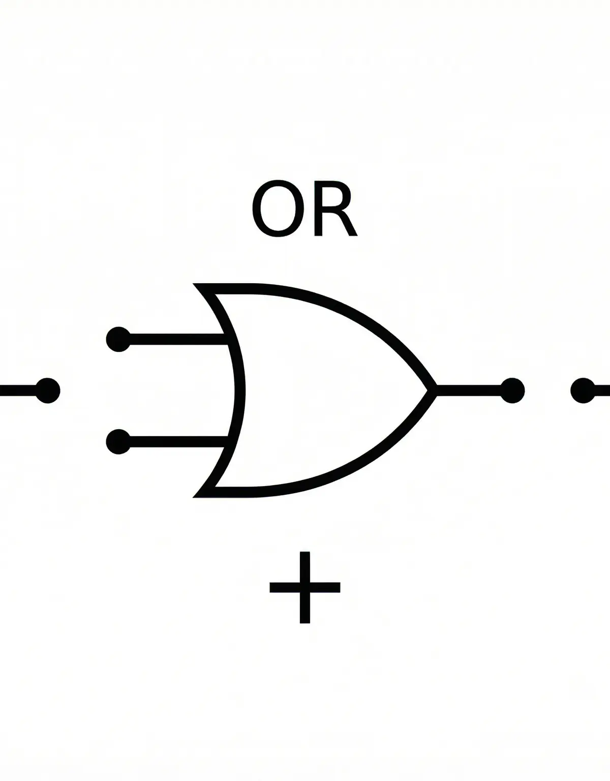
    OR Gate: This gate is more relaxed. The output is 1 if at least one of the inputs is 1. It only outputs 0 if all inputs are 0. Think of it like needing either a bus pass OR a train ticket to use public transport.

    • Symbol: A shield-like shape with a curved back.
    • Boolean Expression: Q = A OR B or Q = A + B

    NOT Gate (Inverter): The simplest of all. It has only one input and one output, and its job is to flip the input value. If the input is 1, the output is 0. If the input is 0, the output is 1.

    • Symbol: A triangle with a small circle (the 'inverter bubble') at its point.
    • Boolean Expression: Q = NOT A or Q = Ā

    logic_gates_symbols.png

    Concept 2: Truth Tables

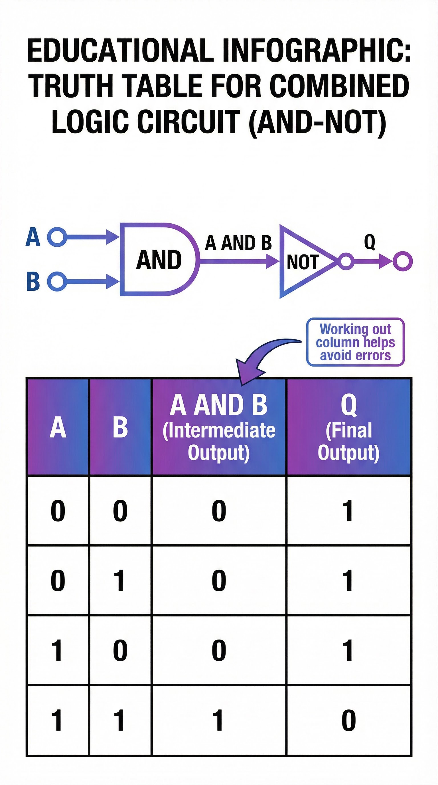
    A truth table is a mathematical table used in logic to compute the functional values of logical expressions on each of their functional arguments. In simpler terms, it’s a way of systematically listing every possible input combination for a logic circuit and showing what the output will be for each one. For a circuit with 'n' inputs, there will be 2^n possible combinations. For the GCSE, you will typically deal with 2 or 3 inputs, resulting in 4 or 8 rows in your truth table.

    Example: A 2-input AND gate truth table.

    ABQ (A AND B)
    000
    010
    100
    111

    Examiners award marks for each correctly completed output row, so accuracy is vital. Always follow the standard binary counting pattern (00, 01, 10, 11) to ensure you don't miss any combinations.
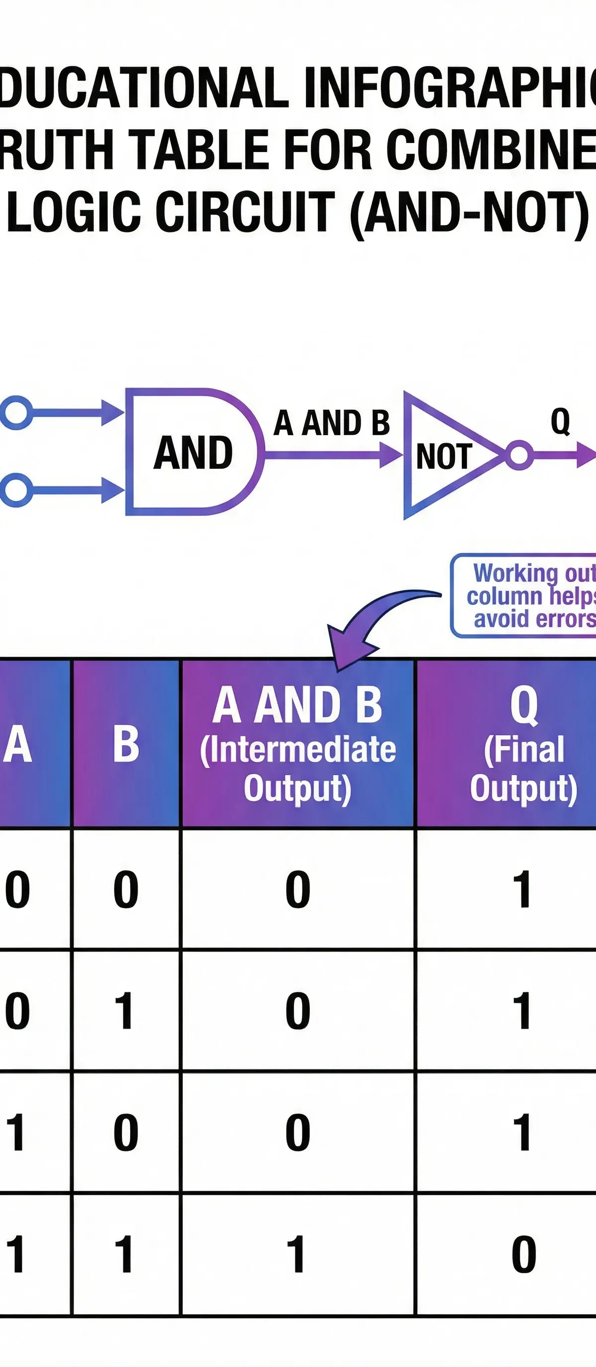
    truth_table_example.png

    Concept 3: Combining Gates & Logic Circuits

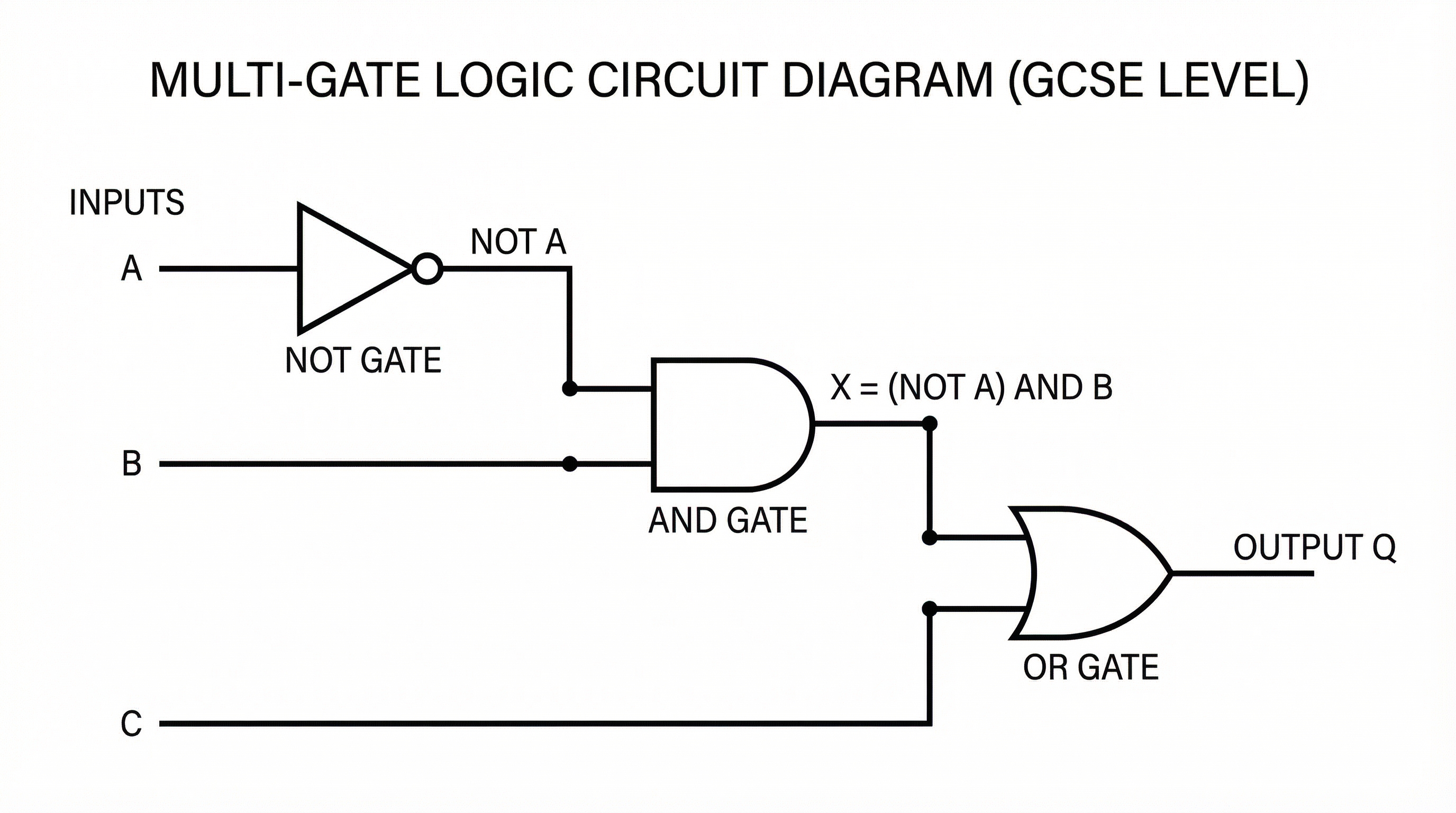
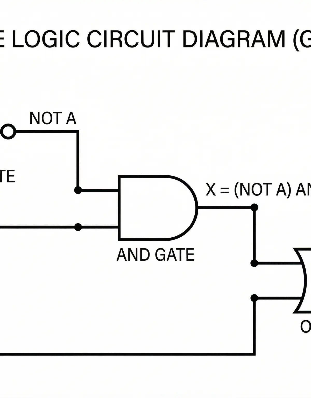
    The real power of Boolean logic comes from combining these simple gates to create complex circuits that can perform useful functions. OCR exams will require you to analyse circuits with multiple gates and determine the final output for a given set of inputs.

    Order of Precedence: When evaluating a complex logical expression, there is a set order of operations, just like BIDMAS in maths.

    1. NOT (operations inside brackets are always done first)
    2. AND
    3. ORFor example, in the expression Q = (A OR B) AND NOT C, you would first evaluate A OR B and NOT C separately, and then you would AND the results together. Using brackets is essential to avoid ambiguity and ensure you follow the logic intended by the circuit diagram.
    logic_circuit_example.png

    Mathematical/Scientific Relationships

    Boolean algebra has its own set of mathematical laws that can be used to simplify complex expressions. While you don't need to memorise all of these for GCSE, understanding the concepts is useful.

    • Commutative Law: A AND B is the same as B AND A. A OR B is the same as B OR A.
    • Associative Law: (A AND B) AND C is the same as A AND (B AND C).
    • Distributive Law: A AND (B OR C) is the same as (A AND B) OR (A AND C).

    These relationships are the foundation of how circuit designers can simplify complex hardware, making it cheaper and more efficient.

    Practical Applications

    Every single decision made by a computer is an application of Boolean logic. Here are a few examples:

    • CPU (Central Processing Unit): The Arithmetic Logic Unit (ALU) within the CPU uses complex logic circuits to perform calculations like addition, subtraction, and comparison.
    • Memory (RAM): Logic gates are used to create flip-flop circuits, which can store a single bit of information (a 1 or a 0). Millions of these together form your computer's memory.
    • Search Engines: When you search for "cats" AND "dogs", the search engine is using a logical AND operation to find pages containing both terms."
    Visual Resources

    3 diagrams and illustrations

    Diagram 1
    Diagram 2
    Diagram 3

    Worked Examples

    3 detailed examples with solutions and examiner commentary

    Practice Questions

    Test your understanding — click to reveal model answers

    Q1

    Draw the standard symbol for a 2-input OR gate. [1 mark]

    1 marks
    foundation

    Hint: Remember the shape is like a shield, not a letter D.

    Q2

    Complete the truth table for a 2-input AND gate. [3 marks]

    3 marks
    foundation

    Hint: The output is only 1 when both inputs are 1.

    Q3

    Write the Boolean expression for the following logic circuit. [3 marks]
    (Diagram shows inputs A and B going to an OR gate, and the output of that OR gate going with input C into an AND gate)

    3 marks
    standard

    Hint: Remember the order of operations. What happens first? Use brackets to show this.

    Q4

    A car has a warning light (Q) that turns on if the driver is not wearing a seatbelt (A=0) AND the engine is on (B=1). Write the Boolean expression and draw the logic circuit. [4 marks]

    4 marks
    challenging

    Hint: How do you represent 'not wearing a seatbelt' (A=0) using a logic gate?

    Q5

    Complete the truth table for the expression P = A XOR B. Note: XOR stands for 'Exclusive OR', where the output is 1 if the inputs are different. [4 marks]

    4 marks
    challenging

    Hint: XOR is not a basic gate, but you can work it out from the definition. The output is 1 only if A is 1 and B is 0, or if A is 0 and B is 1.