AQA · A-Level · Physics
Course version: 7408 · Version from Sept 2016
Construction and deduction of a logic circuit from a truth table.
Full specification wording
Combinational logic (A-level only): Construction and deduction of a logic circuit from a truth table.
A truth table lists every combination of inputs and the required output, so it fully defines a combinational function.
Checked against the AQA 7408 specification (opens in a new tab) on .
- Point 3 of 4
- 2 key terms
Study notes
From the checked teaching notes for this specification point.
The idea
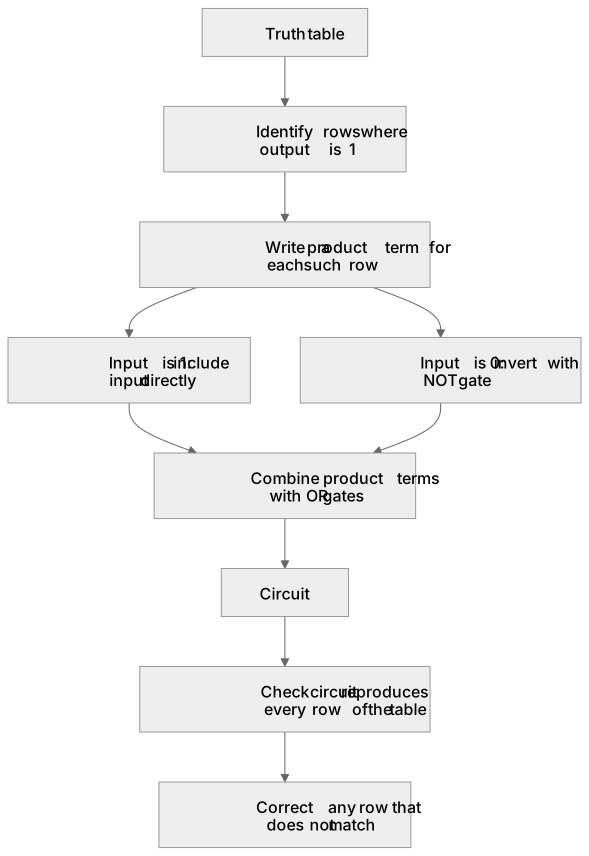
A truth table lists every combination of inputs and the required output, so it fully defines a combinational function. To construct a circuit, identify each row where the output is 1, write a product term that is true only for that row (using AND gates and NOT gates for inputs that are 0), then OR the terms together. For example, output 1 for A = 0, B = 1 gives the term NOT A AND B. To deduce a truth table from a given circuit diagram, work through each gate in order, tabulating intermediate values for all input combinations until the final output column is complete. Both directions rely on the same link between rows, product terms and gates, and on checking that the finished circuit reproduces every row of the table.
What earns the marks
- Identify all input combinations for which the required output is 1 and treat each as one product term.
- Combine the product terms with OR gates to form the complete expression for the output.
- When deducing a truth table from a circuit, label intermediate gate outputs and evaluate them for every input combination.
- Check the final column against the given truth table and correct any row that does not match.
- Use the same systematic row-by-row method whether constructing a circuit or deducing its behaviour.
Common mistakes and how to put them right
Writing a product term for rows where the output is 0 instead of 1.
Put it right by selecting only the rows whose output is 1.
Forgetting to invert an input that is 0 in a selected row.
Put it right by placing a NOT gate on that input in the product term.
Evaluating a circuit in the wrong order or ignoring gate precedence.
Put it right by working stage by stage from the inputs towards the output.
Exam tips
- Draw a column for every intermediate gate output so your working can be followed and checked.
- After building or deducing a circuit, test at least one row where the output is 0 as well as rows where it is 1.
- Keep the number of gates minimal where possible, but always prioritise a circuit that matches the truth table exactly.
Try the lesson
The start of the Combinational logic (A-level only): Construction and deduction of a logic circuit from a truth table. lesson, made from checked teaching notes for this specification point.
Have a go first
A truth table for a logic circuit with inputs A and B shows that the output Q is 1 only when A = 1 and B = 0. Which Boolean expression represents this logic circuit?
Listen
A truth table lists every combination of inputs and the required output, so it fully defines a combinational function. To construct a circuit, identify each row where the output is 1, write a product term that is true only for that row (using AND gates and NOT gates for inputs that are 0), then OR the terms together. For example, output 1 for A = 0, B = 1 gives the term NOT A AND B. To deduce a truth table from a given circuit diagram, work through each gate in order, tabulating intermediate values for all input combinations until the final output column is complete. Both directions rely on the same link between rows, product terms and gates, and on checking that the finished circuit reproduces every row of the table. A strong answer earns marks for these points. Identify all input combinations for which the required output is 1 and treat each as one product term. Combine the product terms with OR gates to form the complete expression for the output. When deducing a truth table from a circuit, label intermediate gate outputs and evaluate them for every input combination. Check the final column against the given truth table and correct any row that does not match. A common slip: Writing a product term for rows where the output is 0 instead of 1. Instead, selecting only the rows whose output is 1. Exam tip: Draw a column for every intermediate gate output so your working can be followed and checked.
See it
Key words
Say what each word means before you turn the card.
Product term
Try answering aloud or in your head before turning the card.
Verification
Try answering aloud or in your head before turning the card.
See every definition
- Product term
- A term that is true only for one row of a truth table, written using AND gates and NOT gates for inputs that are 0.
- Verification
- Checking that the finished circuit reproduces every row of the table and correcting any row that does not match.
Label the diagram
Some boxes have lost their names. Pick the right name for each number.
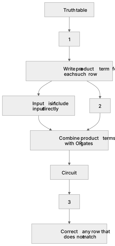
1Box 1
2Box 2
3Box 3
There is more to this lesson
The full lesson goes on to check your understanding and help you earn the marks. Create a free account to carry on, with your progress saved.
A week of Premium from your first lesson · Then the free plan continues · No card, no charge
Test your understanding of Combinational logic (A-level only): Construction and deduction of a logic circuit from a truth table.
Active recall beats re-reading. Take an instant quiz now to test what you’ve learned and lock it into long-term memory.
A week of Premium from your first lesson · Then the free plan continues · No card, no charge