AQA · A-Level · Physics
Course version: 7408 · Version from Sept 2016
Use in photo-conductive mode as a detector in optical systems.
Full specification wording
Photodiode (A-level only): Use in photo-conductive mode as a detector in optical systems.
In photo-conductive mode the photodiode is reverse biased and its conductivity rises when light creates electron-hole pairs, so it acts as a light-controlled current source.
Checked against the AQA 7408 specification (opens in a new tab) on .
- Point 2 of 3
- 4 key terms
Study notes
From the checked teaching notes for this specification point.
The idea
In photo-conductive mode the photodiode is reverse biased and its conductivity rises when light creates electron-hole pairs, so it acts as a light-controlled current source. A load resistor or transimpedance amplifier converts the photocurrent into a measurable voltage. The detector is chosen so its spectral response matches the source wavelength, for example a silicon photodiode for near-infrared or visible light and an indium gallium arsenide device for longer wavelengths. Response time depends on junction capacitance and load resistance, so a smaller load resistor gives a faster but smaller signal. Optical systems use this arrangement in fibre-optic receivers, barcode scanners, smoke detectors and light-beam intruder alarms, where the photocurrent must track rapid changes in light intensity.
What earns the marks
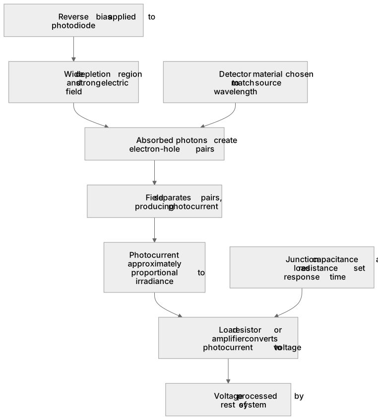
- States that photo-conductive mode uses reverse bias, giving a wide depletion region and a strong electric field across the junction.
- Explains that absorbed photons create electron-hole pairs, which are separated by the field and produce a photocurrent.
- Describes the photocurrent as approximately proportional to irradiance over the intended operating range.
- Explains that a load resistor or amplifier converts the photocurrent into a voltage that can be processed by the rest of the system.
- Relates the choice of detector material to the spectral response matching the wavelength of the optical source.
- Discusses response time in terms of junction capacitance and load resistance, noting the trade-off between speed and signal size.
- Applies the detector to a named optical system, such as a fibre-optic receiver, barcode reader or beam-break alarm.
Common mistakes and how to put them right
Confusing photo-conductive mode with photovoltaic mode.
Put it right by stating that photo-conductive mode uses reverse bias and an external supply, whereas photovoltaic mode uses no external bias.
Assuming the output voltage is independent of the load resistor.
Put it right by using V = IR to show that the same photocurrent gives a larger voltage across a larger load resistance.
Ignoring the wavelength match between source and detector.
Put it right by checking the spectral response curve and choosing a material whose peak response covers the source wavelength.
Exam tips
- Name the mode explicitly and state the bias condition before describing how the photocurrent is produced.
- Include a simple circuit diagram with the reverse bias supply, photodiode and load resistor, and mark the output voltage across the load.
- When discussing speed, refer to the RC time constant of the junction capacitance and load resistance rather than giving a vague claim about fast response.
Try the lesson
The start of the Photodiode (A-level only): Use in photo-conductive mode as a detector in optical systems. lesson, made from checked teaching notes for this specification point.
Have a go first
In which bias condition is a photodiode operated when used in photo-conductive mode as a detector?
Listen
In photo-conductive mode the photodiode is reverse biased and its conductivity rises when light creates electron-hole pairs, so it acts as a light-controlled current source. A load resistor or transimpedance amplifier converts the photocurrent into a measurable voltage. The detector is chosen so its spectral response matches the source wavelength, for example a silicon photodiode for near-infrared or visible light and an indium gallium arsenide device for longer wavelengths. Response time depends on junction capacitance and load resistance, so a smaller load resistor gives a faster but smaller signal. Optical systems use this arrangement in fibre-optic receivers, barcode scanners, smoke detectors and light-beam intruder alarms, where the photocurrent must track rapid changes in light intensity. A strong answer earns marks for these points. States that photo-conductive mode uses reverse bias, giving a wide depletion region and a strong electric field across the junction. Explains that absorbed photons create electron-hole pairs, which are separated by the field and produce a photocurrent. Describes the photocurrent as approximately proportional to irradiance over the intended operating range. Explains that a load resistor or amplifier converts the photocurrent into a voltage that can be processed by the rest of the system. A common slip: Confusing photo-conductive mode with photovoltaic mode. Instead, stating that photo-conductive mode uses reverse bias and an external supply, whereas photovoltaic mode uses no external bias. Exam tip: Name the mode explicitly and state the bias condition before describing how the photocurrent is produced.
See it
Key words
Say what each word means before you turn the card.
Photo-conductive mode
Try answering aloud or in your head before turning the card.
Photocurrent
Try answering aloud or in your head before turning the card.
Spectral response
Try answering aloud or in your head before turning the card.
RC time constant
Try answering aloud or in your head before turning the card.
See every definition
- Photo-conductive mode
- Uses reverse bias and an external supply, giving a wide depletion region and a strong electric field across the junction.
- Photocurrent
- Produced when absorbed photons create electron-hole pairs, which are separated by the field; approximately proportional to irradiance over the intended operating range.
- Spectral response
- Chosen so it matches the wavelength of the optical source, for example a silicon photodiode for near-infrared or visible light.
- RC time constant
- Of the junction capacitance and load resistance determines response time, so a smaller load resistor gives a faster but smaller signal.
Label the diagram
Some boxes have lost their names. Pick the right name for each number.
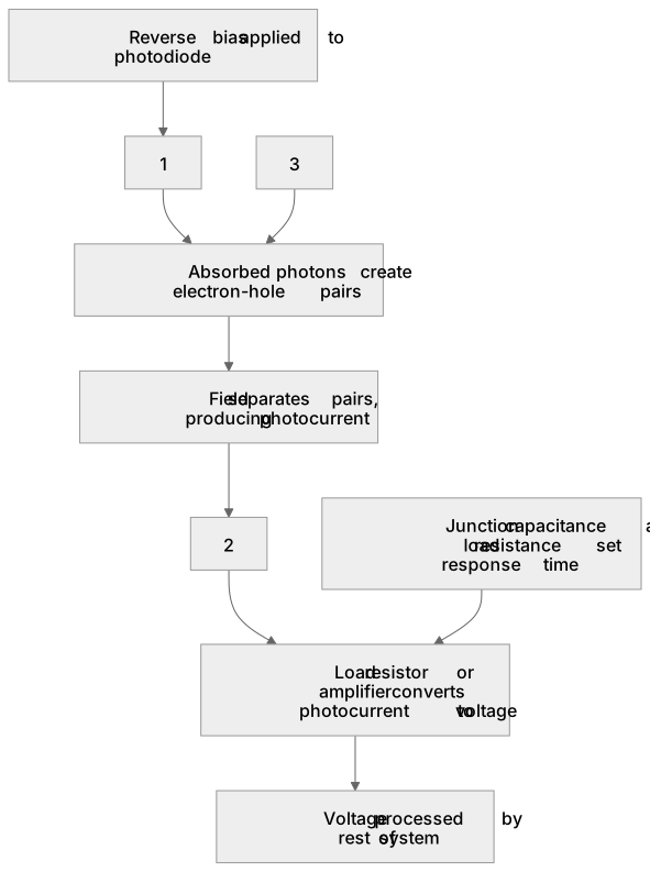
1Box 1
2Box 2
3Box 3
There is more to this lesson
The full lesson goes on to check your understanding and help you earn the marks. Create a free account to carry on, with your progress saved.
A week of Premium from your first lesson · Then the free plan continues · No card, no charge
Test your understanding of Photodiode (A-level only): Use in photo-conductive mode as a detector in optical systems.
Active recall beats re-reading. Take an instant quiz now to test what you’ve learned and lock it into long-term memory.
A week of Premium from your first lesson · Then the free plan continues · No card, no charge