AQA · A-Level · Physics
Course version: 7408 · Version from Sept 2016
Examples should include the use of variable resistors, thermistors, and…
Full specification wording
Potential divider: Examples should include the use of variable resistors, thermistors, and light dependent resistors (LDR) in the potential divider.
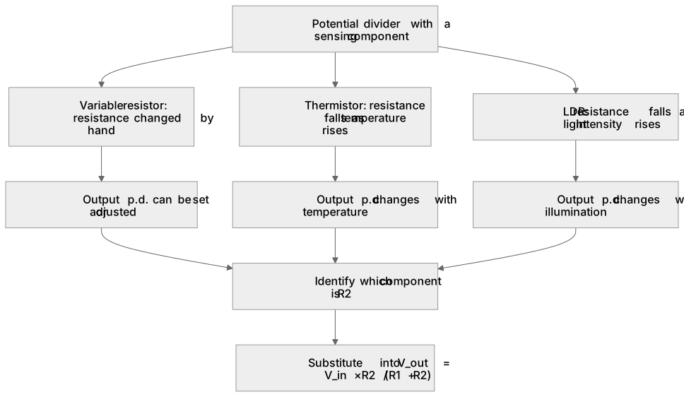
A variable resistor changes its resistance by hand, so the output p.d. can be set or adjusted.
Checked against the AQA 7408 specification (opens in a new tab) on .
- Point 2 of 2
- 4 key terms
Study notes
From the checked teaching notes for this specification point.
The idea
A variable resistor changes its resistance by hand, so the output p.d. can be set or adjusted. A thermistor's resistance falls as temperature rises (negative temperature coefficient), so in a divider its output p.d. changes with temperature. An LDR's resistance falls as light intensity rises, so its output p.d. changes with illumination. In each case use V_out = V_in × R₂ / (R₁ + R₂), where R₂ is the resistor across which the output is taken.
For example: With a 6.0 V supply, a fixed 2.0 kΩ resistor and a thermistor of resistance 4.0 kΩ, the p.d. across the thermistor is 6.0 × 4000 / 6000 = 4.0 V. Decide which component is R₂, then substitute.
What earns the marks
- Applies V_out = V_in × R₂ / (R₁ + R₂) to circuits containing a variable resistor, thermistor or LDR.
- Explains that a variable resistor allows the output p.d. to be adjusted manually.
- Explains that a thermistor's resistance decreases as temperature increases, changing the output p.d.
- Explains that an LDR's resistance decreases as light intensity increases, changing the output p.d.
- Identifies which component the output p.d. is measured across before calculating.
Common mistakes and how to put them right
Reversing the thermistor or LDR resistance trend.
Put it right by remembering that resistance falls as temperature or light intensity rises.
Taking the output across the wrong component.
Put it right by stating which resistor is R₂ before substituting into the equation.
Mixing resistance units; correct this by converting all resistances to the same unit, such as ohms or kilohms, before calculating.
Exam tips
- Name the sensing component and state how its resistance changes before doing the calculation.
- Write the divider equation, identify R₂, then substitute values with units.
- For explain questions, link the resistance change to the change in share of the supply p.d. across each component.
Try the lesson
The start of the Potential divider: Examples should include the use of variable resistors, thermistors, and light dependent resistors (LDR) in the potential divider. lesson, made from checked teaching notes for this specification point.
Have a go first
In a potential divider, an NTC (negative temperature coefficient) thermistor is connected in series with a fixed resistor across a constant supply. As the thermistor gets hotter, what happens to its resistance and to the potential difference across it?
Listen
A variable resistor changes its resistance by hand, so the output p.d. can be set or adjusted. A thermistor's resistance falls as temperature rises (negative temperature coefficient), so in a divider its output p.d. changes with temperature. An LDR's resistance falls as light intensity rises, so its output p.d. changes with illumination. In each case use V_out = V_in × R₂ / (R₁ + R₂), where R₂ is the resistor across which the output is taken. For example, with a 6.0 V supply, a fixed 2.0 kΩ resistor and a thermistor of resistance 4.0 kΩ, the p.d. across the thermistor is 6.0 × 4000 / 6000 = 4.0 V. Decide which component is R₂, then substitute. A strong answer earns marks for these points. Applies V_out = V_in × R₂ / (R₁ + R₂) to circuits containing a variable resistor, thermistor or LDR. Explains that a variable resistor allows the output p.d. to be adjusted manually. Explains that a thermistor's resistance decreases as temperature increases, changing the output p.d. Explains that an LDR's resistance decreases as light intensity increases, changing the output p.d. A common slip: Reversing the thermistor or LDR resistance trend. Instead, remembering that resistance falls as temperature or light intensity rises. Exam tip: Name the sensing component and state how its resistance changes before doing the calculation.
See it
Key words
Say what each word means before you turn the card.
variable resistor
Try answering aloud or in your head before turning the card.
thermistor
Try answering aloud or in your head before turning the card.
LDR
Try answering aloud or in your head before turning the card.
R₂
Try answering aloud or in your head before turning the card.
See every definition
- variable resistor
- A component that changes its resistance by hand, so the output p.d. can be set or adjusted.
- thermistor
- A component whose resistance falls as temperature rises, so in a divider its output p.d. changes with temperature.
- LDR
- A component whose resistance falls as light intensity rises, so its output p.d. changes with illumination.
- R₂
- The resistor across which the output is taken, used in V_out = V_in × R₂ / (R₁ + R₂).
Label the diagram
Some boxes have lost their names. Pick the right name for each number.
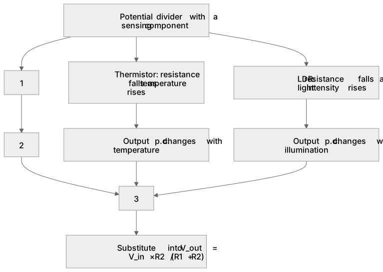
1Box 1
2Box 2
3Box 3
There is more to this lesson
The full lesson goes on to check your understanding and help you earn the marks. Create a free account to carry on, with your progress saved.
A week of Premium from your first lesson · Then the free plan continues · No card, no charge
Test your understanding of Potential divider: Examples should include the use of variable resistors, thermistors, and light dependent resistors (LDR) in the potential divider.
Active recall beats re-reading. Take an instant quiz now to test what you’ve learned and lock it into long-term memory.
A week of Premium from your first lesson · Then the free plan continues · No card, no charge