AQA · A-Level · Physics
Course version: 7408 · Version from Sept 2016
Inputs to the circuits, clock, reset, up/down.
Full specification wording
Sequential logic (A-level only): Inputs to the circuits, clock, reset, up/down.
Sequential counting circuits are controlled by several inputs.
Checked against the AQA 7408 specification (opens in a new tab) on .
- Point 2 of 5
- 4 key terms
Study notes
From the checked teaching notes for this specification point.
The idea
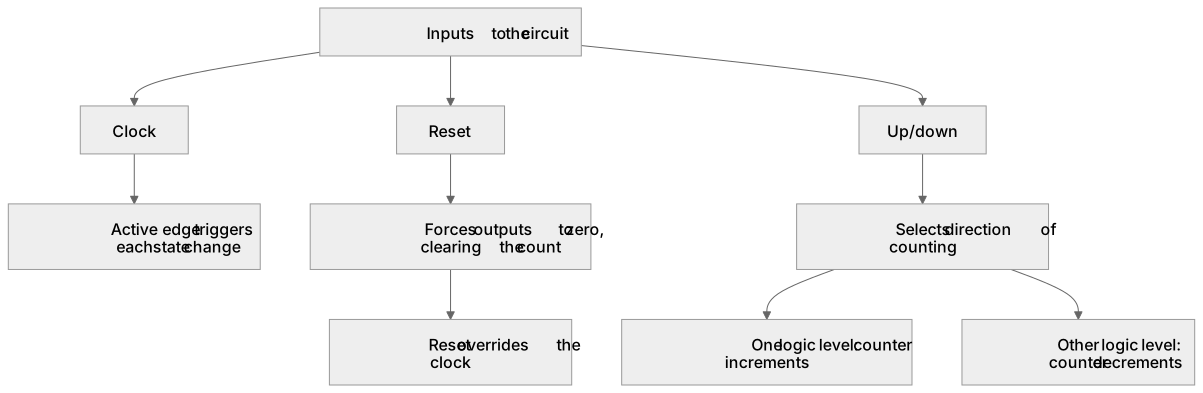
Sequential counting circuits are controlled by several inputs. The clock is the continuous square-wave signal whose active edge triggers each state change; without it the circuit holds its current state. The reset input asynchronously or synchronously forces all outputs to zero, clearing the count to 0000 regardless of the current state. The up/down input selects the direction of counting: when it is at one logic level the counter increments, and at the other level it decrements, so the same circuit can count forwards or backwards. You analyse these inputs by tracing how each one affects the next-state logic, for example showing that a reset pulse overrides the clock and returns a 3-bit counter to 000, while changing up/down reverses the sequence from 000, 001, 010 to 000, 111, 110.
What earns the marks
- Identifies the clock as the input that synchronises state changes and states that the active edge triggers each transition.
- Explains that the reset input clears the counter outputs to zero, either immediately or on the next active clock edge depending on the design.
- Describes the up/down input as selecting whether the counter increments or decrements on each clock pulse.
- Traces the effect of each control input on the next-state table or output sequence of a given circuit.
- Explains the priority of reset over normal counting when both reset and clock signals are present.
Common mistakes and how to put them right
Treating the clock as a level-sensitive input rather than an edge-triggered one.
Put it right: State changes occur only on the specified active edge.
Assuming reset always acts immediately.
Put it right: Some counters reset synchronously on the next clock edge, so the design must be checked.
Believing that up/down changes the clock frequency.
Put it right: It changes the direction of the count sequence, not the timing.
Exam tips
- Label the clock, reset and up/down inputs clearly on any circuit diagram before tracing the sequence.
- State the active edge, for example rising or falling, whenever you describe when the count changes.
- Use a short timing diagram or state table to show how reset and up/down alter the sequence, rather than describing it only in words.
Try the lesson
The start of the Sequential logic (A-level only): Inputs to the circuits, clock, reset, up/down. lesson, made from checked teaching notes for this specification point.
Have a go first
Which input to a sequential counting circuit causes the stored count to return immediately to zero?
Listen
Sequential counting circuits are controlled by several inputs. The clock is the continuous square-wave signal whose active edge triggers each state change; without it the circuit holds its current state. The reset input asynchronously or synchronously forces all outputs to zero, clearing the count to 0000 regardless of the current state. The up/down input selects the direction of counting: when it is at one logic level the counter increments, and at the other level it decrements, so the same circuit can count forwards or backwards. You analyse these inputs by tracing how each one affects the next-state logic, for example showing that a reset pulse overrides the clock and returns a 3-bit counter to 000, while changing up/down reverses the sequence from 000, 001, 010 to 000, 111, 110. A strong answer earns marks for these points. Identifies the clock as the input that synchronises state changes and states that the active edge triggers each transition. Explains that the reset input clears the counter outputs to zero, either immediately or on the next active clock edge depending on the design. Describes the up/down input as selecting whether the counter increments or decrements on each clock pulse. Traces the effect of each control input on the next-state table or output sequence of a given circuit. A common slip: Treating the clock as a level-sensitive input rather than an edge-triggered one. Instead, state changes occur only on the specified active edge. Exam tip: Label the clock, reset and up/down inputs clearly on any circuit diagram before tracing the sequence.
See it
Key words
Say what each word means before you turn the card.
Clock
Try answering aloud or in your head before turning the card.
Reset input
Try answering aloud or in your head before turning the card.
Up/down input
Try answering aloud or in your head before turning the card.
Next-state logic
Try answering aloud or in your head before turning the card.
See every definition
- Clock
- The continuous square-wave signal whose active edge triggers each state change; without it the circuit holds its current state.
- Reset input
- Forces all outputs to zero, clearing the count to 0000 regardless of the current state, either asynchronously or synchronously.
- Up/down input
- Selects the direction of counting: at one logic level the counter increments, and at the other level it decrements.
- Next-state logic
- The logic analysed by tracing how each input affects it, for example showing that a reset pulse overrides the clock.
Label the diagram
Some boxes have lost their names. Pick the right name for each number.
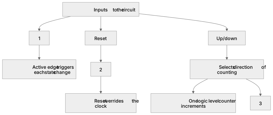
1Box 1
2Box 2
3Box 3
There is more to this lesson
The full lesson goes on to check your understanding and help you earn the marks. Create a free account to carry on, with your progress saved.
A week of Premium from your first lesson · Then the free plan continues · No card, no charge
Test your understanding of Sequential logic (A-level only): Inputs to the circuits, clock, reset, up/down.
Active recall beats re-reading. Take an instant quiz now to test what you’ve learned and lock it into long-term memory.
A week of Premium from your first lesson · Then the free plan continues · No card, no charge