Pearson Edexcel · A-Level · Physics
Materials
Master the fundamentals of electric circuits, from current and resistance to complex potential dividers. This topic is heavily tested in calculation and graph interpretation questions, making it essential for securing top grades.
- 4 min read
- 3 worked examples
- 5 practice questions
- 6 key terms
Study Notes
Overview
Welcome to Electric Circuits! This topic forms the backbone of GCSE Physics. It explores how charge flows, how energy is transferred, and how different components behave when connected together. Understanding circuits is crucial not only for your exam but also for understanding the technology that powers our modern world.
Examiners love testing this topic through multi-step calculations, I-V graph interpretations, and explanations of how changing one component affects the rest of the circuit. You'll need a solid grasp of key formulas, the ability to apply Ohm's law, and a clear understanding of the difference between series and parallel circuits.
Key Concepts
Concept 1: Current, Charge, and Potential Difference
Electric Current (I) is the rate of flow of electric charge. It's measured in Amperes (A). Think of it like the volume of water flowing through a pipe every second.
Potential Difference (V), or voltage, is the energy transferred per unit charge. It's the 'push' that causes the current to flow, measured in Volts (V).
Resistance (R) is the opposition to the flow of current, measured in Ohms (\Omega). A higher resistance means it's harder for current to flow.
Concept 2: Series vs Parallel Circuits
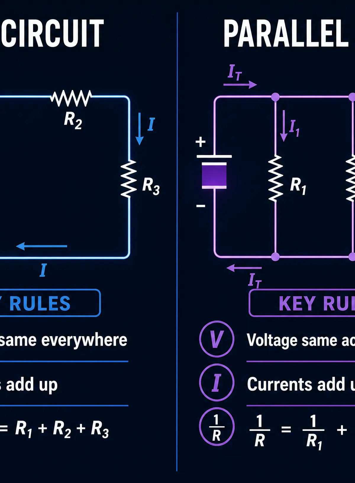
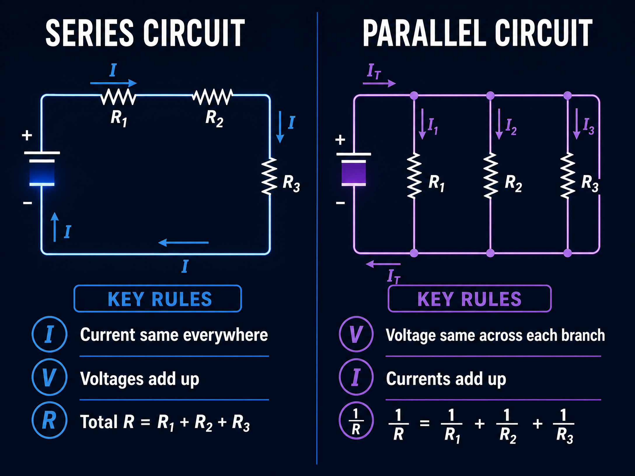
Understanding the rules for series and parallel circuits is fundamental.
In a Series Circuit, there is only one path for the current. Therefore, the current is the same everywhere. The total potential difference is shared between the components, and the total resistance is the sum of the individual resistances (R_{total} = R_1 + R_2 + ...).
In a Parallel Circuit, there are multiple branches. The potential difference across each branch is the same as the source. The total current splits between the branches. Adding resistors in parallel decreases the total resistance, calculated using \frac{1}{R_{total}} = \frac{1}{R_1} + \frac{1}{R_2} + ...
Concept 3: I-V Characteristics
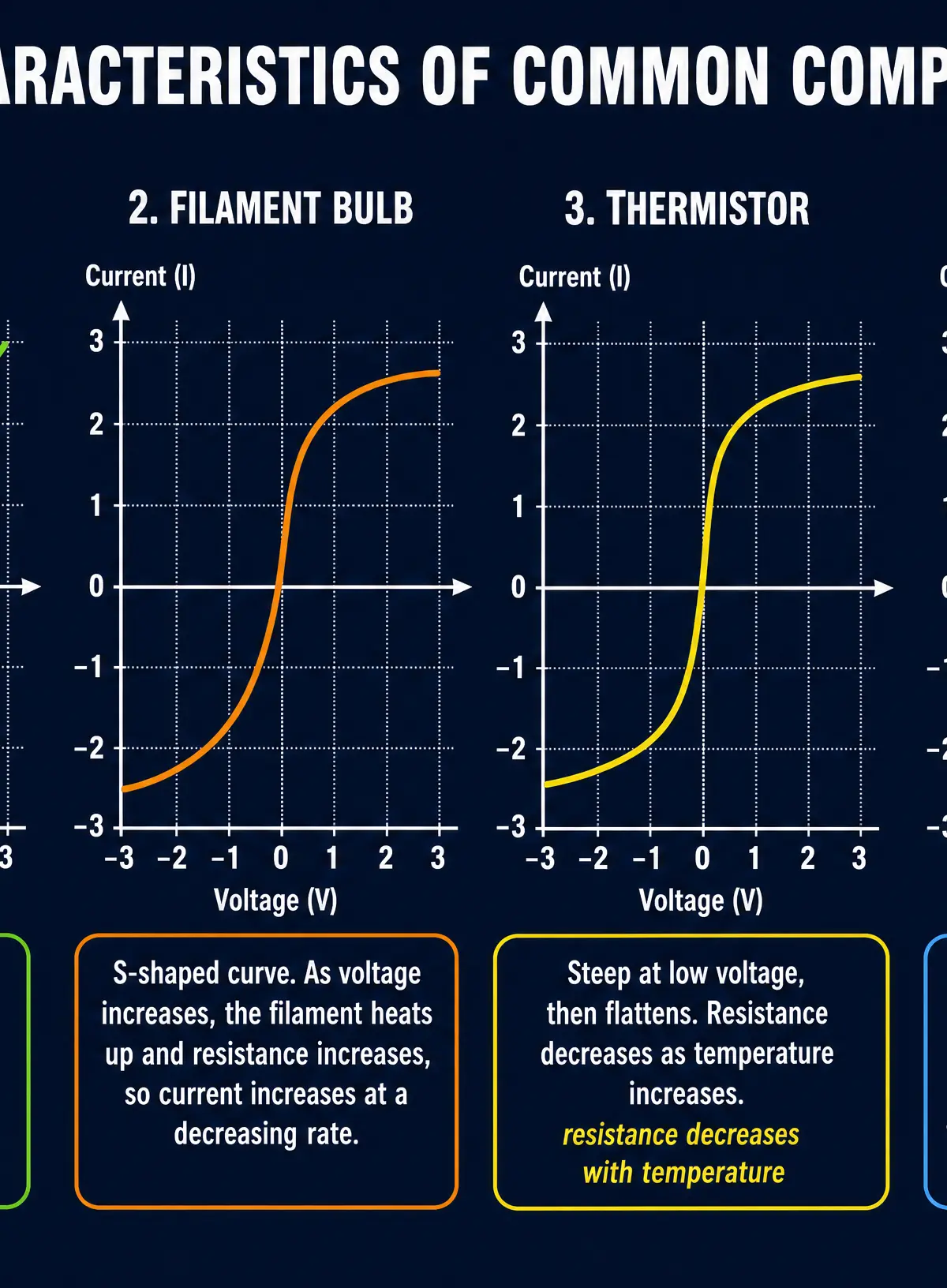
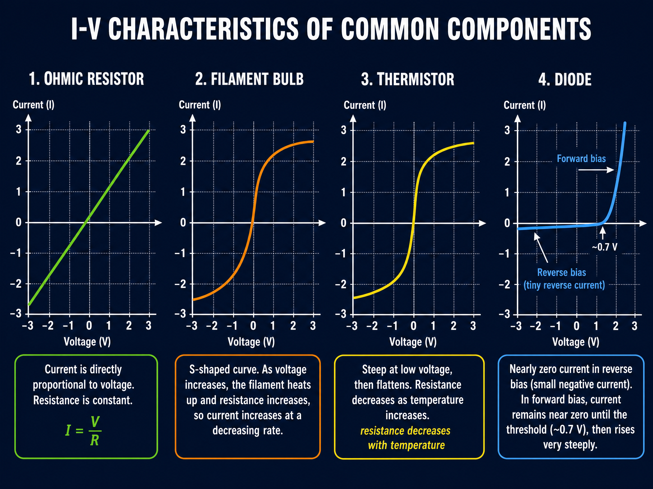
Examiners frequently ask you to interpret or sketch Current-Voltage (I-V) graphs for different components.
- Ohmic Conductor (e.g., fixed resistor at constant temperature): Current is directly proportional to potential difference. The graph is a straight line through the origin.
- Filament Bulb: As current increases, temperature increases, causing resistance to increase. The graph is an 'S' shape, flattening at higher voltages.
- Diode: Only allows current to flow in one direction (forward bias). The graph shows zero current until a threshold voltage (~0.7V), then a steep rise.
- Thermistor/LDR: Resistance decreases as temperature/light intensity increases.
Concept 4: Resistivity and Advanced Models
The resistance of a wire depends on its material and dimensions: R = \frac{\rho l}{A}.
- \rho is resistivity (an intrinsic property of the material).
- l is length (longer wire = higher resistance).
- A is cross-sectional area (thicker wire = lower resistance).
For Higher Tier candidates, the drift velocity equation I = nqvA relates macroscopic current to the microscopic movement of charge carriers.
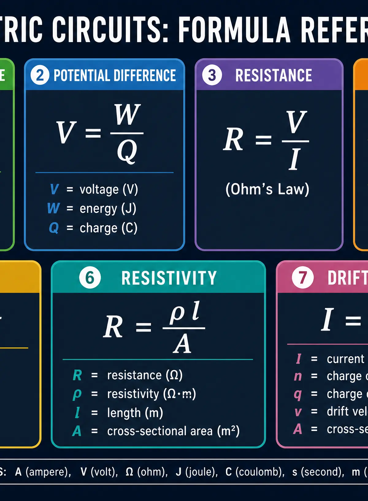
Mathematical/Scientific Relationships
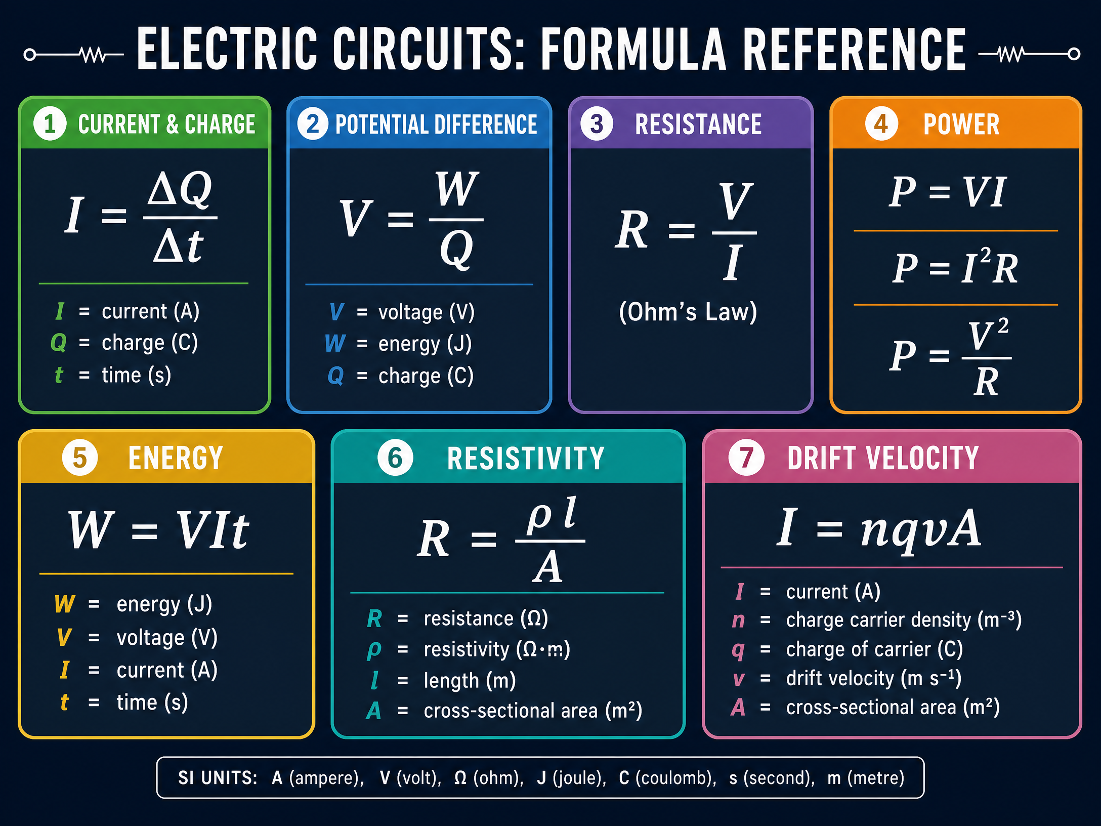
- I = \frac{\Delta Q}{\Delta t} (Current = Charge / Time)
- V = \frac{W}{Q} (Potential Difference = Energy / Charge)
- R = \frac{V}{I} (Ohm's Law)
- P = VI = I^2R = \frac{V^2}{R} (Electrical Power)
- W = VIt (Electrical Energy)
- R = \frac{\rho l}{A} (Resistivity)
- I = nqvA (Drift Velocity - Higher Tier)
Practical Applications
Required Practical: Investigating ResistanceCandidates must know how to set up a circuit to measure the V and I for a component to determine its resistance. Key steps include using a variable resistor to change the current, taking multiple readings, and plotting an I-V graph. A common error is leaving the circuit switched on between readings, which heats the wire and changes its resistance.
Visual Resources
3 diagrams and illustrations
Interactive Diagrams
2 interactive diagrams to visualise key concepts
Conceptual Flow Outline
Decision tree for determining component I-V characteristics.
Conceptual Flow Outline
Rules for Voltage and Current in Series and Parallel Circuits.
Worked Examples
3 worked examples — open one to explore the question and available guidance.
Practice Questions
Test your understanding — click to reveal model answers
A 12V car battery supplies a current of 5.0A to the headlights. Calculate the power of the headlights.
Hint: Use the formula that links Power, Voltage, and Current.
A charge of 45C flows through a resistor in 3.0 minutes. Calculate the current.
Hint: Check the units for time before you calculate.
Explain how the resistance of an LDR changes as light intensity increases, and describe one practical use for an LDR.
Hint: Think about automatic lighting systems.
A wire has a length of 2.5m, a cross-sectional area of 1.2 × 10^-6 m², and a resistance of 0.035 Ω. Calculate the resistivity of the metal.
Hint: You need to rearrange the resistivity formula to make ρ the subject.
Two identical resistors are connected in parallel to a 9V supply. The total current from the supply is 3.0A. Calculate the resistance of one of the resistors.
Hint: Find the total resistance first, then use the parallel rule for identical resistors.
Test your understanding of Materials
Active recall beats re-reading. Take an instant quiz now to test what you’ve learned and lock it into long-term memory.
7 days Premium · Then free forever · No card, no charge