Pearson Edexcel · A-Level · Physics
Mechanics
Master the fundamentals of Electric Circuits, a cornerstone of GCSE Physics that appears in almost every exam paper. This comprehensive guide covers everything from Ohm's Law and I-V characteristics to parallel circuits and power calculations, equipping you with the exact knowledge examiners reward.
- 7 min read
- 3 worked examples
- 5 practice questions
- 6 key terms
Study Notes
Overview
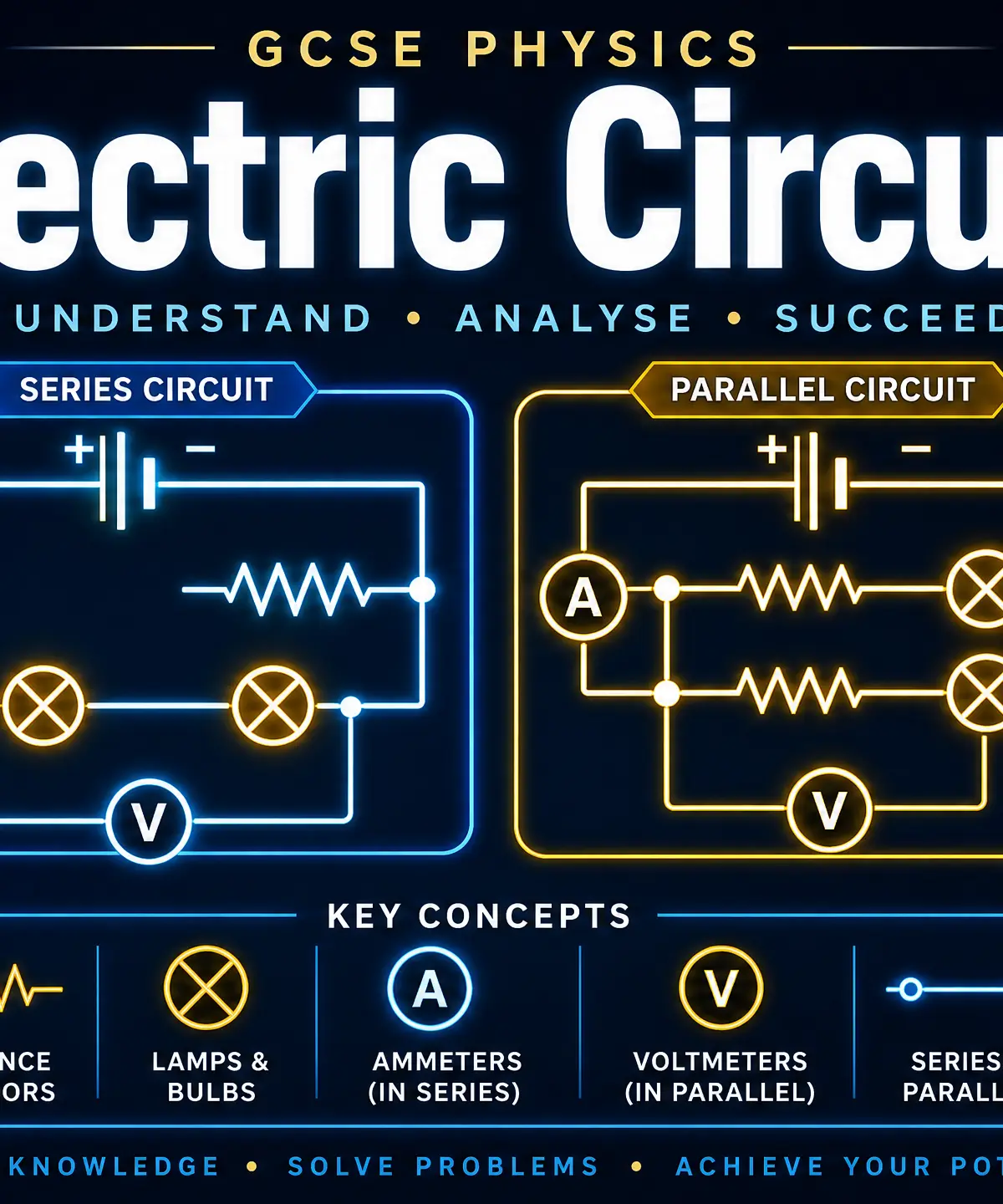
Electric Circuits is a fundamental topic in GCSE Physics, underpinning much of our modern technological world. Understanding how charge flows, how energy is transferred, and how components interact is essential not only for your exam but for comprehending everything from the smartphone in your pocket to the national grid.
This topic is heavily tested across all exam boards, often appearing in both multiple-choice questions and extended 6-mark calculations. Examiners particularly love to test your ability to apply formulas (like V = IR and P = VI), interpret I-V graphs for non-ohmic components, and distinguish between series and parallel circuit rules.
By mastering these concepts, you'll secure a significant portion of the marks available on your paper. Let's dive in and break down exactly what you need to know.
Listen to the Podcast
Listen to our 12-minute deep dive into Electric Circuits, featuring clear explanations, common exam pitfalls, and a quick-fire recall quiz!
Key Concepts
Concept 1: Current, Charge, and Time
Electric current (I) is defined as the rate of flow of electrical charge. For a current to flow, you need two things: a closed circuit and a source of potential difference (like a cell or battery). Current is measured in Amperes (A) using an ammeter connected in series.
Charge (Q) is carried by electrons in solid metal conductors. It is measured in Coulombs (C).
The Relationship:
I = \frac{\Delta Q}{\Delta t}
Why it works: Think of charge like water in a pipe, and current as the speed at which the water is flowing past a specific point every second.
Example: If 24\text{ C} of charge flows through a lamp in 12\text{ s}, the current is I = 24 / 12 = 2\text{ A}.
Concept 2: Potential Difference (Voltage)
Potential difference (V), often called voltage, is the energy transferred per unit charge passed. It is the "push" that causes charge to flow. We measure it in Volts (V) using a voltmeter connected in parallel across a component.
The Relationship:
V = \frac{W}{Q}
(Where W is work done or energy transferred in Joules)
Why it works: If current is the flow of water, potential difference is the pressure from the pump. A higher voltage means each Coulomb of charge is carrying more energy.
Concept 3: Resistance and Ohm's Law
Resistance (R) is the opposition to the flow of current. It is measured in Ohms (\Omega).
Ohm's Law states that for an ohmic conductor at a constant temperature, the current through it is directly proportional to the potential difference across it.
The Relationship:
V = I \times R
Example: A resistor has a resistance of 100,\Omega. If a potential difference of 12\text{ V} is applied across it, the current is I = V / R = 12 / 100 = 0.12\text{ A}.
Concept 4: I-V Characteristics
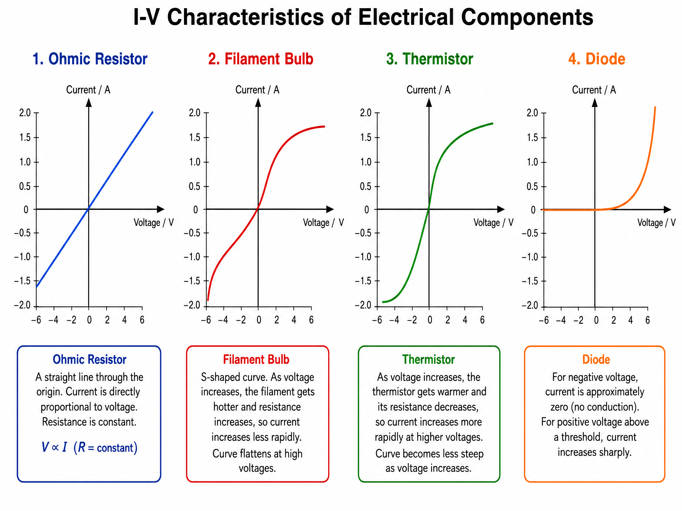
Examiners frequently ask you to interpret Current-Voltage (I-V) graphs for different components.
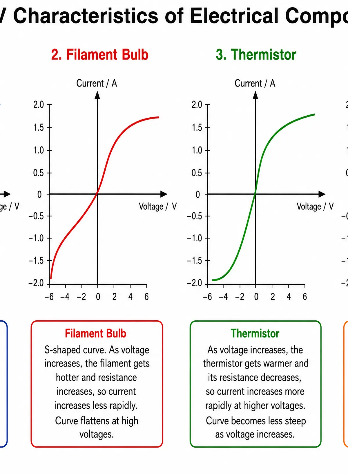
- Ohmic Conductor (Resistor at constant temperature): A straight line passing through the origin. Current is directly proportional to voltage.
- Filament Lamp: An 'S' shaped curve. As current increases, the temperature of the filament increases. This causes the resistance to increase (the atoms vibrate more, causing more collisions with electrons), so the curve gets flatter at higher voltages.
- Diode: Current only flows in one direction (forward bias). It has very high resistance in the reverse direction.
- Thermistor: A temperature-dependent resistor. In hot conditions, resistance decreases. In cold conditions, resistance increases.
- LDR (Light Dependent Resistor): In bright light, resistance decreases. In darkness, resistance is highest.
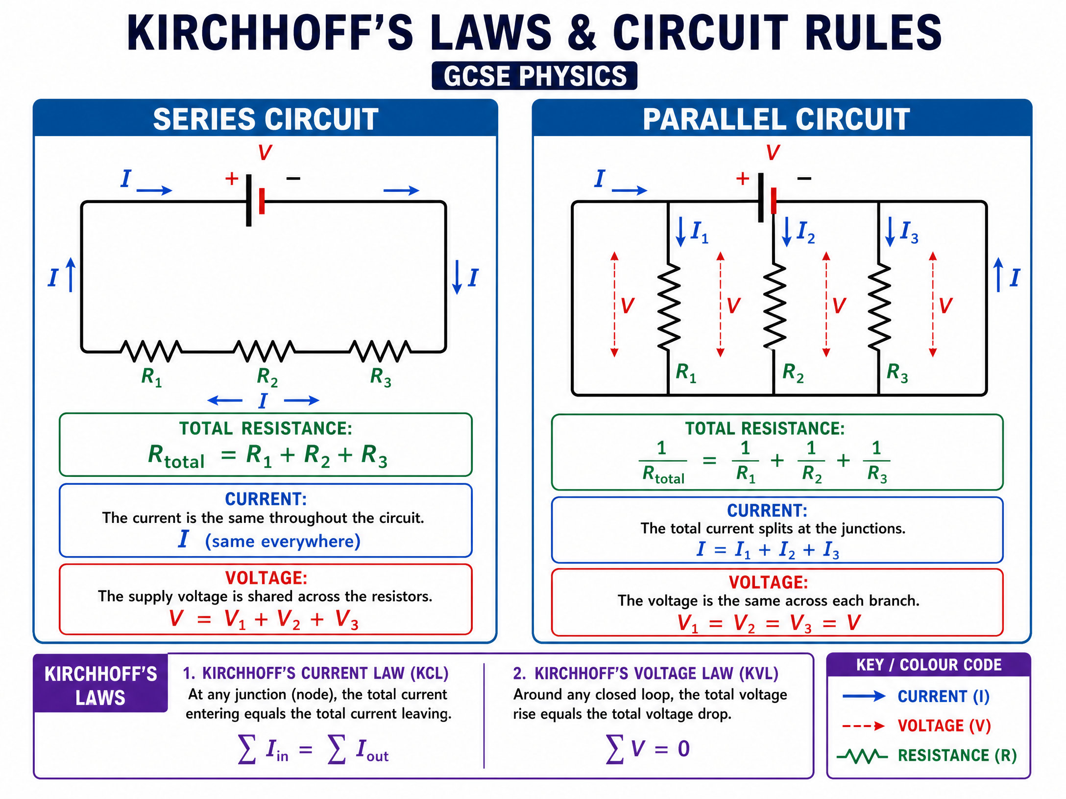
Concept 5: Series and Parallel Circuits
Understanding the rules for series and parallel circuits is crucial for calculation questions.
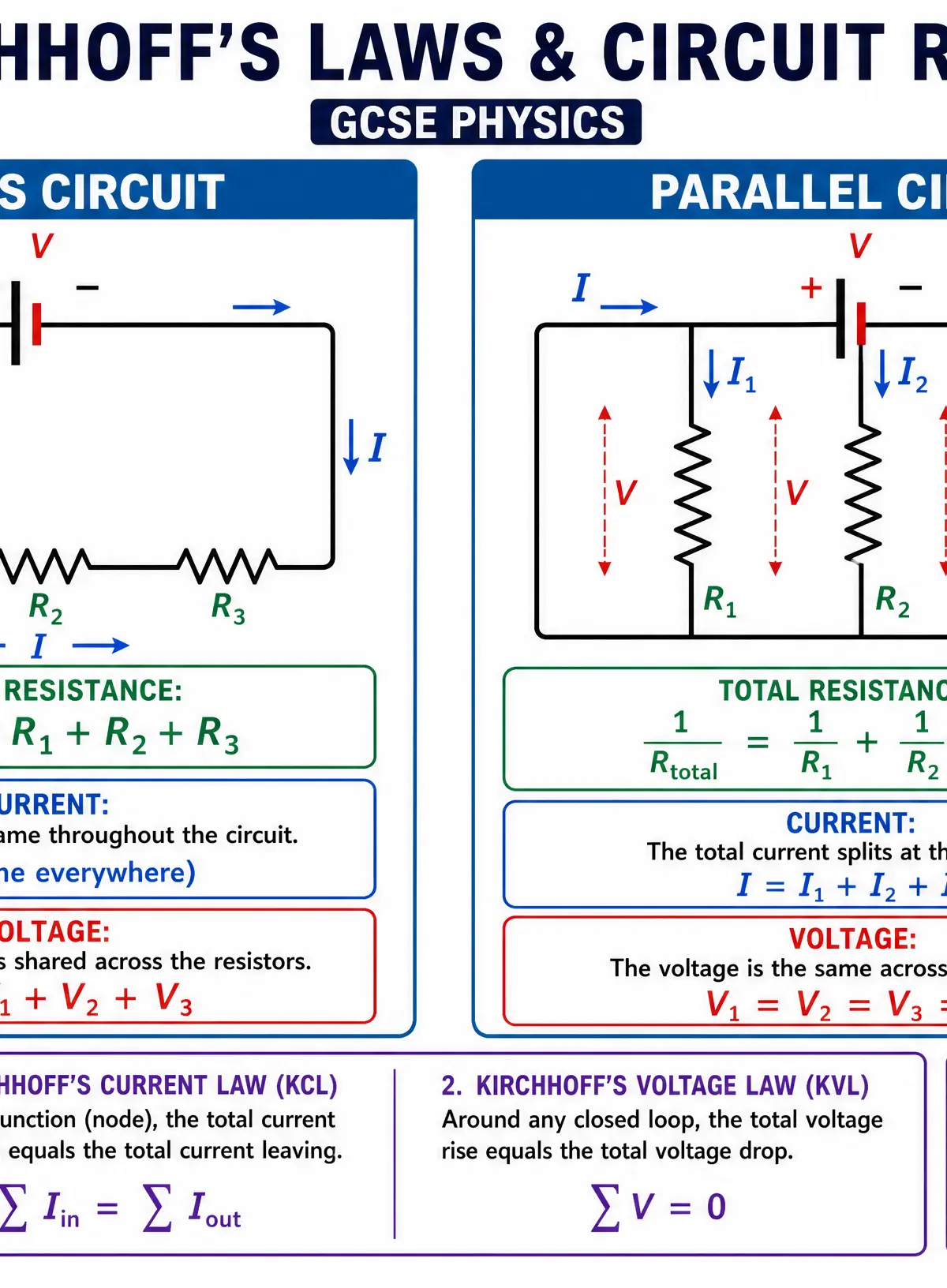
Series Circuits:
- Current: The same everywhere (I_1 = I_2 = I_3).
- Potential Difference: Shared between components (V_{total} = V_1 + V_2 + ...).
- Resistance: Adds up (R_{total} = R_1 + R_2 + ...).
Parallel Circuits:
- Current: Splits down different branches (I_{total} = I_1 + I_2 + ...).
- Potential Difference: The same across all branches (V_1 = V_2 = V_3).
- Resistance: Adding resistors in parallel decreases the total resistance. (Higher tier formula: \frac{1}{R_{total}} = \frac{1}{R_1} + \frac{1}{R_2} + ...)
Concept 6: Power and Energy
Power (P) is the rate at which energy is transferred, measured in Watts (W). There are three key equations for electrical power that you must be able to use and derive from one another:
- P = V \times I
- P = I^2 \times R (Derived by substituting V = IR into the first equation)
- P = \frac{V^2}{R} (Derived by substituting I = \frac{V}{R} into the first equation)
Energy transferred (E or W) can be calculated by multiplying power by time (E = P \times t), which gives us:
E = V \times I \times t
Concept 7: Electromotive Force (e.m.f.) and Internal Resistance (Higher Tier)
E.m.f. is the total energy supplied by the cell per Coulomb of charge. However, the voltage actually delivered to the circuit (the terminal potential difference) is always slightly less than the e.m.f. when current is flowing.
Why? Because the battery itself has some internal resistance (r). Some energy is dissipated as heat inside the battery.
The Relationship:
V_{terminal} = \varepsilon - (I \times r)
Mathematical/Scientific Relationships
| Formula | Meaning | Units | Status |
|---|---|---|---|
| $I = \frac{\Delta Q}{\Delta t}$ | Current = Charge / Time | $I$ in A, $Q$ in C, $t$ in s | Must memorise |
| $V = \frac{W}{Q}$ | Voltage = Work done / Charge | $V$ in V, $W$ in J, $Q$ in C | Must memorise |
| $V = I \times R$ | Voltage = Current $\times$ Resistance | $V$ in V, $I$ in A, $R$ in $\Omega$ | Must memorise |
| $P = V \times I$ | Power = Voltage $\times$ Current | $P$ in W, $V$ in V, $I$ in A | Must memorise |
| $P = I^2 \times R$ | Power = Current$^2$ $\times$ Resistance | $P$ in W, $I$ in A, $R$ in $\Omega$ | Must memorise |
| $E = V \times I \times t$ | Energy = Voltage $\times$ Current $\times$ Time | $E$ in J, $V$ in V, $I$ in A, $t$ in s | Must memorise |
| $R = \frac{\rho l}{A}$ | Resistance = (Resistivity $\times$ length) / Area | $R$ in $\Omega$, $\rho$ in $\Omega$m, $l$ in m, $A$ in m$^2$ | Given on formula sheet (Higher) |
Practical Applications
Required Practical: Investigating Resistance
- Aim: To investigate how the length of a wire affects its resistance.
- Apparatus: Power supply, ammeter, voltmeter, metre ruler, crocodile clips, resistance wire.
- Method: Connect the wire to the circuit using crocodile clips at 0\text{ cm} and 10\text{ cm}. Record current and voltage. Calculate resistance using R = V/I. Move the second clip to 20\text{ cm}, repeat, and continue up to 100\text{ cm}.
- Expected Results: Resistance is directly proportional to length (a straight line through the origin on a graph of R vs L).
- Common Errors: The wire heating up increases its resistance, skewing results. Solution: Keep the current low and switch off the circuit between readings.
Real World Application: Thermistors and LDRsThermistors are used in thermostats to control central heating. As the room cools, resistance increases, which can be used to trigger the heating to turn on. LDRs are used in automatic streetlights; as it gets dark, resistance increases, triggering the lights to switch on.
Visual Resources
2 diagrams and illustrations
Interactive Diagrams
2 interactive diagrams to visualise key concepts
Conceptual Flow Outline
A flowchart showing the systematic approach to solving Physics calculation questions.
Conceptual Flow Outline
A process map explaining why a filament lamp is non-ohmic.
Worked Examples
3 worked examples — open one to explore the question and available guidance.
Practice Questions
Test your understanding — click to reveal model answers
A charge of 45 C flows through a resistor in 1.5 minutes. Calculate the current.
Hint: Check the units for time.
Two resistors, 10 Ω and 15 Ω, are connected in series to a 12 V battery. Calculate the potential difference across the 10 Ω resistor.
Hint: Find the total resistance first, then the total current.
Describe and explain the shape of the I-V characteristic graph for a diode.
Hint: Talk about both the positive and negative sides of the voltage axis.
A thermistor is connected in series with a fixed resistor and a battery. A voltmeter is connected across the fixed resistor. Explain what happens to the reading on the voltmeter when the temperature of the thermistor increases.
Hint: Think about how the total resistance of the circuit changes, and how that affects the total current.
A 5.0 m length of copper wire has a cross-sectional area of 2.0 × 10^-6 m^2. The resistivity of copper is 1.7 × 10^-8 Ωm. Calculate the resistance of the wire.
Hint: Use the formula R = ρl/A.
Test your understanding of Mechanics
Active recall beats re-reading. Take an instant quiz now to test what you’ve learned and lock it into long-term memory.
7 days Premium · Then free forever · No card, no charge