Pearson Edexcel · A-Level · Physics
Working as a Physicist
Master the fundamentals of electric circuits, from Ohm's Law and I-V characteristics to the rules governing series and parallel circuits. This high-yield topic forms the foundation for many multi-mark calculation questions and practical application scenarios in your GCSE Physics exam.
- 5 min read
- 3 worked examples
- 5 practice questions
- 6 key terms
Study Notes
Overview

Electric circuits are the lifeblood of modern technology, powering everything from your smartphone to national power grids. In this topic, you will explore the fundamental principles that govern how electricity flows, how energy is transferred, and how different components respond to electrical current.
Understanding electric circuits is crucial for your GCSE Physics exam because it combines conceptual understanding with mathematical problem-solving. Examiners frequently test this topic through multi-part calculation questions, circuit diagram analysis, and explanations of component behaviour. This topic synoptically links to energy transfers, the particle model of matter, and electromagnetism. Mastering the rules for series and parallel circuits, alongside Ohm's Law, will secure you significant marks across both multiple-choice and extended-response questions.
Key Concepts
Concept 1: Current, Charge, and Potential Difference
Current (I) is the rate of flow of electric charge. In solid metallic conductors, this charge is carried by tiny, negatively charged electrons. Think of current as the volume of water flowing through a pipe every second. Current is measured in amperes (A) using an ammeter connected in series.
Potential Difference (V), often called voltage, is the energy transferred per unit of charge passing between two points in a circuit. It acts as the "push" that drives the current around the circuit. Potential difference is measured in volts (V) using a voltmeter connected in parallel across a component.
Charge (Q) is a fundamental property of matter. The total charge that flows is determined by the current and how long it flows for. Charge is measured in coulombs (C).
Concept 2: Resistance and Ohm's Law
Resistance (R) is a measure of how much a component opposes the flow of electric current. When electrons move through a conductor, they collide with the positive ions in the metal lattice, transferring kinetic energy (which is why wires get hot). Resistance is measured in ohms (\Omega).
Ohm's Law states that for an ohmic conductor (like a fixed resistor) at a constant temperature, the current is directly proportional to the potential difference across it. This means if you double the voltage, the current doubles, and the resistance remains constant.
Concept 3: Series and Parallel Circuits

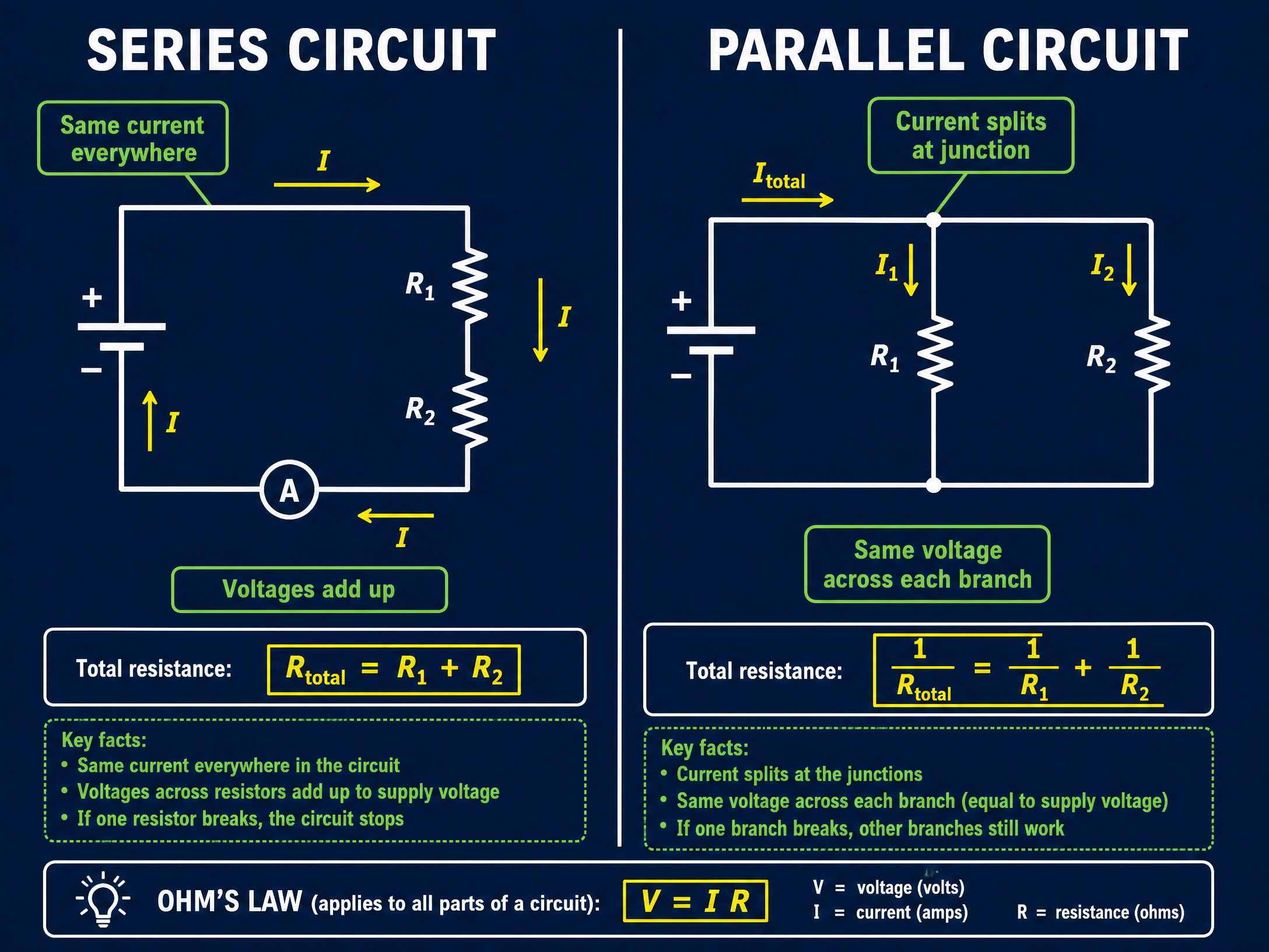
Series Circuits consist of a single loop.
- Current: The same everywhere (I_{total} = I_1 = I_2).
- Potential Difference: Shared between components (V_{total} = V_1 + V_2).
- Resistance: Adds up (R_{total} = R_1 + R_2).
Parallel Circuits contain multiple branches.
- Current: Splits at junctions (I_{total} = I_1 + I_2).
- Potential Difference: The same across each branch (V_{total} = V_1 = V_2).
- Resistance: Adding resistors in parallel decreases the total resistance, as there are more paths for the current to flow through.
Concept 4: I-V Characteristics
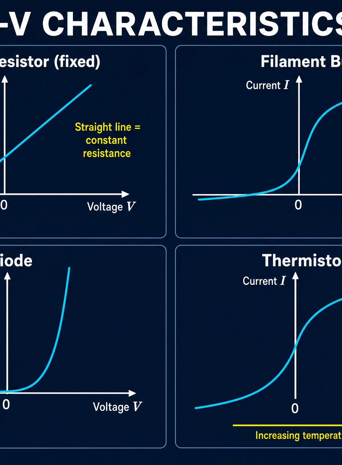
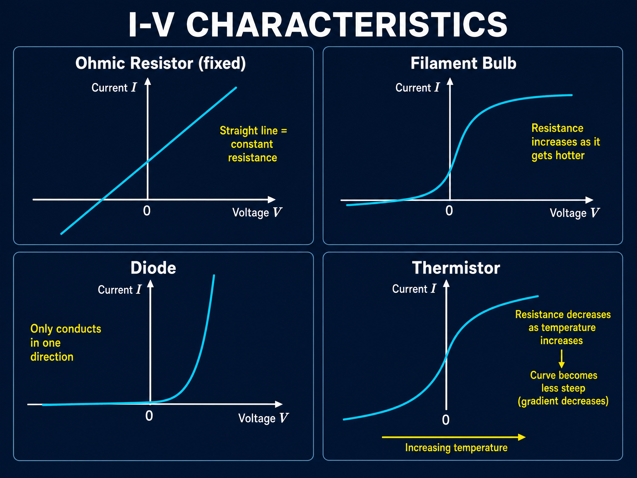
An I-V characteristic graph shows how the current through a component varies with the potential difference across it.
- Ohmic Conductor: A straight line passing through the origin. Resistance is constant.
- Filament Bulb: An 'S' shaped curve. As current increases, temperature increases, causing resistance to increase (the gradient decreases).
- Diode: Only allows current to flow in one direction. It has a very high resistance in the reverse direction.
Concept 5: Thermistors and LDRs
- Thermistor: A temperature-dependent resistor. As temperature increases, its resistance decreases. Useful in thermostats.
- LDR (Light Dependent Resistor): As light intensity increases, its resistance decreases. Useful in automatic streetlights.
Mathematical/Scientific Relationships

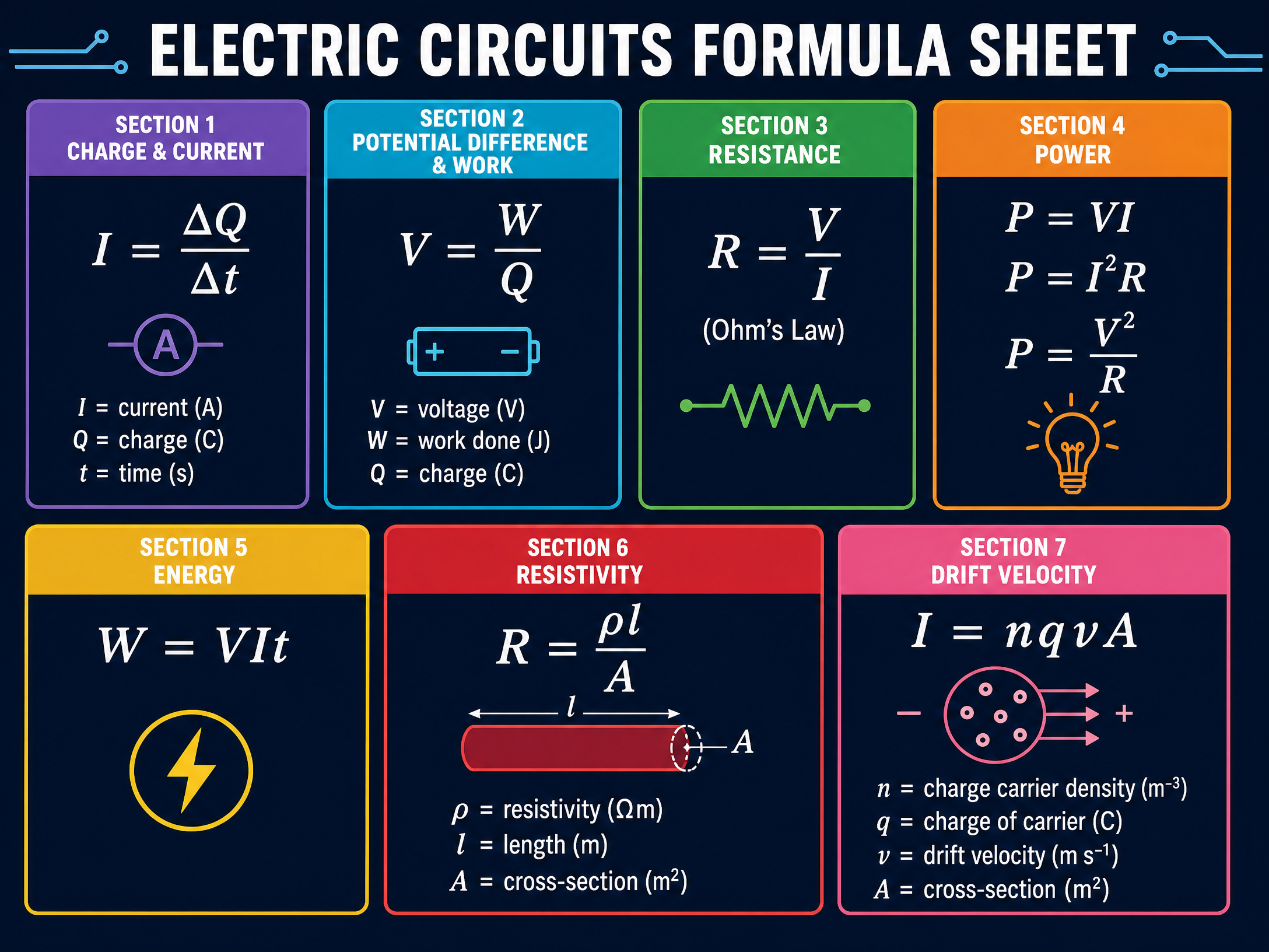
- Charge Flow: Q = I \times t (Charge = Current \times Time)
- Potential Difference: V = E / Q (Potential Difference = Energy / Charge)
- Ohm's Law: V = I \times R (Potential Difference = Current \times Resistance)
- Power (Electrical): P = V \times I (Power = Potential Difference \times Current)
- Power (Resistance): P = I^2 \times R (Power = Current^2 \times Resistance)
- Energy Transferred: E = P \times t or E = V \times I \times t
Note: Ensure time is always in seconds (s) and power is in watts (W) before calculating.
Practical Applications
Required Practical: Resistance of a WireStudents investigate how the length of a wire affects its resistance.
- Method: Tape a wire to a metre ruler. Connect crocodile clips at various lengths (e.g., 10cm, 20cm). Record V and I. Calculate R.
- Key Precaution: The wire will heat up, increasing its resistance and introducing a systematic error. To mitigate this, keep the current low and turn off the power supply between readings.
Audio RevisionListen to the complete topic overview, common mistakes, and quick-fire quiz:
Visual Resources
3 diagrams and illustrations
Interactive Diagrams
2 interactive diagrams to visualise key concepts
Conceptual Flow Outline
A reliable flowchart for tackling multi-step physics calculations.
Conceptual Flow Outline
The microscopic explanation for why resistance increases with temperature in a filament bulb.
Worked Examples
3 worked examples — open one to explore the question and available guidance.
Practice Questions
Test your understanding — click to reveal model answers
A charge of 45 C flows through a resistor in 30 seconds. Calculate the current. (3 marks)
Hint: Use the QuIT mnemonic: Q = I × t. You need to rearrange for I.
Describe how a student could use a circuit to determine the resistance of a fixed resistor. (4 marks)
Hint: Think about which two instruments you need to measure the values for Ohm's Law, and how they must be connected.
A circuit contains a 12 V battery connected to two resistors in parallel. Resistor A is 6 Ω and Resistor B is 4 Ω. Calculate the total current drawn from the battery. (5 marks)
Hint: You can either find the total resistance first, OR find the current in each branch and add them together.
Explain how the resistance of an LDR changes as light intensity decreases, and give one practical use for an LDR. (3 marks)
Hint: Think about dark conditions. Does it let current flow easily or block it?
A student investigates how the length of a wire affects its resistance. Explain why the student should keep the current low during the experiment. (2 marks)
Hint: What happens to a wire when a high current flows through it, and how does that affect the variable you are trying to measure?
Test your understanding of Working as a Physicist
Active recall beats re-reading. Take an instant quiz now to test what you’ve learned and lock it into long-term memory.
7 days Premium · Then free forever · No card, no charge