OCR · A-Level · Physics
Course version: H556 · Version from Sept 2015
(ii) techniques and procedures used to investigate capacitors in both…
Full specification wording
Capacitors: (ii) techniques and procedures used to investigate capacitors in both series and parallel combinations using ammeters and voltmeters.
Investigating capacitors in series and parallel uses ammeters in series to measure current and voltmeters in parallel to measure p.d. across each component.
Checked against the OCR H556 specification (opens in a new tab) on .
- Point 6 of 6
- 4 key terms
Study notes
From the checked teaching notes for this specification point.
The idea
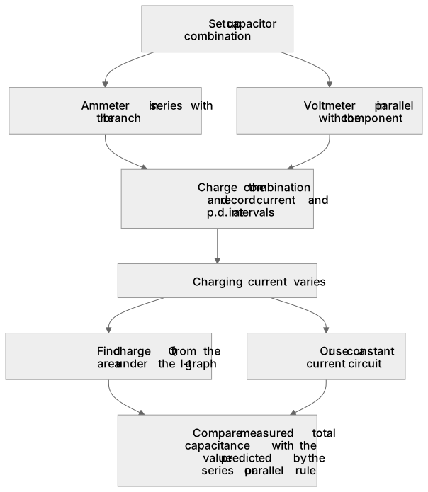
Investigating capacitors in series and parallel uses ammeters in series to measure current and voltmeters in parallel to measure p.d. across each component. For series capacitors, the reciprocal rule 1/C_total = 1/C₁ + 1/C₂ gives a smaller total capacitance; for parallel, C_total = C₁ + C₂ gives a larger total. A practical procedure charges the combination and records current and p.d. at intervals. Because charging current varies, charge Q is found from the area under an I-t graph, not simply Q = It, unless a constant current circuit is used. Correct meter placement matters: an ammeter must be in series with the branch, a voltmeter in parallel. Readings verify the combination rules.
What earns the marks
- Place an ammeter in series with the circuit branch and a voltmeter in parallel with the component being measured.
- Use the series rule 1/C_total = 1/C₁ + 1/C₂ and the parallel rule C_total = C₁ + C₂ for capacitor combinations.
- Record current and p.d. readings over time to determine charge Q from the area under an I-t graph, or use a constant current circuit.
- Compare measured total capacitance with the value predicted by the series or parallel rule.
Common mistakes and how to put them right
Connecting the ammeter in parallel with a component.
Put it right: An ammeter must be in series to measure current.
Connecting the voltmeter in series.
Put it right: A voltmeter must be in parallel with the component whose p.d. is measured.
Using Q = It for a varying current.
Put it right: Charge must be found from the area under the I-t graph unless current is kept constant.
Exam tips
- Draw the circuit diagram clearly, showing ammeter in series and voltmeter in parallel before describing readings.
- State the combination rule you are testing and show the substitution of measured values.
- Explain how to find charge from the area under a current-time graph when describing the procedure.
Try the lesson
The start of the Capacitors: (ii) techniques and procedures used to investigate capacitors in both series and parallel combinations using ammeters and voltmeters. lesson, made from checked teaching notes for this specification point.
Listen
Investigating capacitors in series and parallel uses ammeters in series to measure current and voltmeters in parallel to measure p.d. across each component. For series capacitors, the reciprocal rule 1/C_total = 1/C₁ + 1/C₂ gives a smaller total capacitance; for parallel, C_total = C₁ + C₂ gives a larger total. A practical procedure charges the combination and records current and p.d. at intervals. Because charging current varies, charge Q is found from the area under an I-t graph, not simply Q = It, unless a constant current circuit is used. Correct meter placement matters: an ammeter must be in series with the branch, a voltmeter in parallel. Readings verify the combination rules. A strong answer earns marks for these points. Place an ammeter in series with the circuit branch and a voltmeter in parallel with the component being measured. Use the series rule 1/C_total = 1/C₁ + 1/C₂ and the parallel rule C_total = C₁ + C₂ for capacitor combinations. Record current and p.d. readings over time to determine charge Q from the area under an I-t graph, or use a constant current circuit. Compare measured total capacitance with the value predicted by the series or parallel rule. Exam tip: Draw the circuit diagram clearly, showing ammeter in series and voltmeter in parallel before describing readings.
See it
Key words
Say what each word means before you turn the card.
Meter placement in circuits
Try answering aloud or in your head before turning the card.
Series and parallel capacitor rules
Try answering aloud or in your head before turning the card.
Experimental measurement of charge and p.d.
Try answering aloud or in your head before turning the card.
Verification of predicted total capacitance
Try answering aloud or in your head before turning the card.
See every definition
- Meter placement in circuits
- An ammeter must be in series with the branch, and a voltmeter in parallel with the component being measured.
- Series and parallel capacitor rules
- The series rule 1/C_total = 1/C₁ + 1/C₂ gives a smaller total capacitance, while the parallel rule C_total = C₁ + C₂ gives a larger total.
- Experimental measurement of charge and p.d.
- Current and p.d. readings are recorded over time, and because charging current varies, charge Q is found from the area under an I-t graph, or a constant current circuit is used.
- Verification of predicted total capacitance
- Measured total capacitance is compared with the value predicted by the series or parallel rule, and readings verify the combination rules.
Label the diagram
Some boxes have lost their names. Pick the right name for each number.
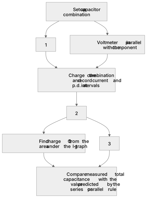
1Box 1
2Box 2
3Box 3
There is more to this lesson
The full lesson goes on to check your understanding and help you earn the marks. Create a free account to carry on, with your progress saved.
A week of Premium from your first lesson · Then the free plan continues · No card, no charge
Test your understanding of Capacitors: (ii) techniques and procedures used to investigate capacitors in both series and parallel combinations using ammeters and voltmeters.
Active recall beats re-reading. Take an instant quiz now to test what you’ve learned and lock it into long-term memory.
A week of Premium from your first lesson · Then the free plan continues · No card, no charge