OCR · A-Level · Physics
Course version: H556 · Version from Sept 2015
Circuit symbols: (b) circuit diagrams using these symbols.
A circuit diagram uses standard symbols joined by straight lines to show how components are connected.
Checked against the OCR H556 specification (opens in a new tab) on .
- Point 2 of 2
- 4 key terms
Study notes
From the checked teaching notes for this specification point.
The idea
A circuit diagram uses standard symbols joined by straight lines to show how components are connected. You must be able to read and interpret a diagram, and to choose the diagram that correctly represents a described circuit. Key ideas are series and parallel connections, the position of meters, and the polarity of cells and diodes. An ammeter is placed in series with the component whose current is being measured, while a voltmeter is placed in parallel across the component whose potential difference is being measured. A diode conducts when the triangle points in the direction of conventional current, from positive to negative. In a multiple-choice question you may be asked which diagram matches a description, or which diagram contains an error such as a voltmeter in series.
What earns the marks
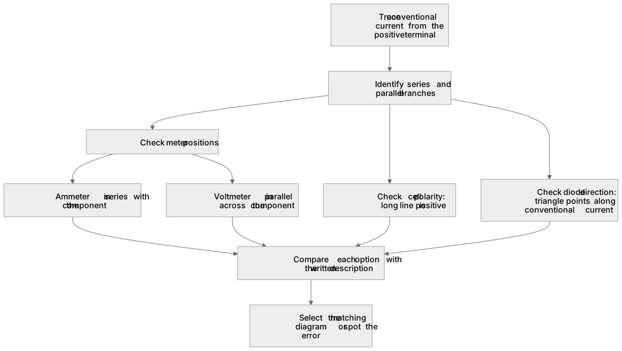
- Interprets a circuit diagram by identifying series and parallel branches and the components in each.
- Places an ammeter in series and a voltmeter in parallel with the correct component.
- Recognises correct cell and battery polarity, with the long line as the positive terminal.
- Identifies the conducting direction of a diode from the orientation of the triangle and bar.
- Selects the diagram that matches a written description of a circuit, or spots the diagram containing a connection error.
Common mistakes and how to put them right
Placing a voltmeter in series with a component.
Put it right: A voltmeter must be connected in parallel across the component being measured.
Placing an ammeter in parallel with a component.
Put it right: An ammeter must be in series so the current to be measured passes through it.
Reversing the cell polarity so the long line is treated as negative.
Put it right: The long line is the positive terminal.
Drawing a diode so that it would block conventional current in the intended direction.
Put it right: The triangle must point along the conventional current direction.
Exam tips
- Trace the conventional current from the positive terminal round the circuit before deciding on connections.
- Check meter positions first, since ammeter and voltmeter placement is a common source of error in diagrams.
- Compare each option against the written description clause by clause rather than choosing the first plausible diagram.
- Redraw a complex diagram in a simpler layout if it helps you see the series and parallel sections.
Try the lesson
The start of the Circuit symbols: (b) circuit diagrams using these symbols. lesson, made from checked teaching notes for this specification point.
Listen
A circuit diagram uses standard symbols joined by straight lines to show how components are connected. You must be able to read and interpret a diagram, and to choose the diagram that correctly represents a described circuit. Key ideas are series and parallel connections, the position of meters, and the polarity of cells and diodes. An ammeter is placed in series with the component whose current is being measured, while a voltmeter is placed in parallel across the component whose potential difference is being measured. A diode conducts when the triangle points in the direction of conventional current, from positive to negative. In a multiple-choice question you may be asked which diagram matches a description, or which diagram contains an error such as a voltmeter in series. A strong answer earns marks for these points. Interprets a circuit diagram by identifying series and parallel branches and the components in each. Places an ammeter in series and a voltmeter in parallel with the correct component. Recognises correct cell and battery polarity, with the long line as the positive terminal. Identifies the conducting direction of a diode from the orientation of the triangle and bar. Exam tip: Trace the conventional current from the positive terminal round the circuit before deciding on connections.
See it
Key words
Say what each word means before you turn the card.
Circuit diagram interpretation
Try answering aloud or in your head before turning the card.
Series and parallel connections
Try answering aloud or in your head before turning the card.
Meter placement
Try answering aloud or in your head before turning the card.
Component polarity
Try answering aloud or in your head before turning the card.
See every definition
- Circuit diagram interpretation
- Reading a diagram that uses standard symbols joined by straight lines to show how components are connected, identifying series and parallel branches and the components in each.
- Series and parallel connections
- The ways components are joined in a circuit, which you must identify when interpreting a diagram or choosing the diagram that correctly represents a described circuit.
- Meter placement
- An ammeter is placed in series with the component whose current is being measured, while a voltmeter is placed in parallel across the component whose potential difference is being measured.
- Component polarity
- The correct orientation of cells and diodes, with the long line as the positive terminal and the diode's triangle pointing in the direction of conventional current, from positive to negative.
Label the diagram
Some boxes have lost their names. Pick the right name for each number.
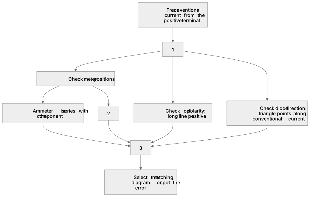
1Box 1
2Box 2
3Box 3
There is more to this lesson
The full lesson goes on to check your understanding and help you earn the marks. Create a free account to carry on, with your progress saved.
A week of Premium from your first lesson · Then the free plan continues · No card, no charge
Test your understanding of Circuit symbols: (b) circuit diagrams using these symbols.
Active recall beats re-reading. Take an instant quiz now to test what you’ve learned and lock it into long-term memory.
A week of Premium from your first lesson · Then the free plan continues · No card, no charge