OCR · A-Level · Physics
Course version: H556 · Version from Sept 2015
Potential dividers: (a) potential divider circuit with components
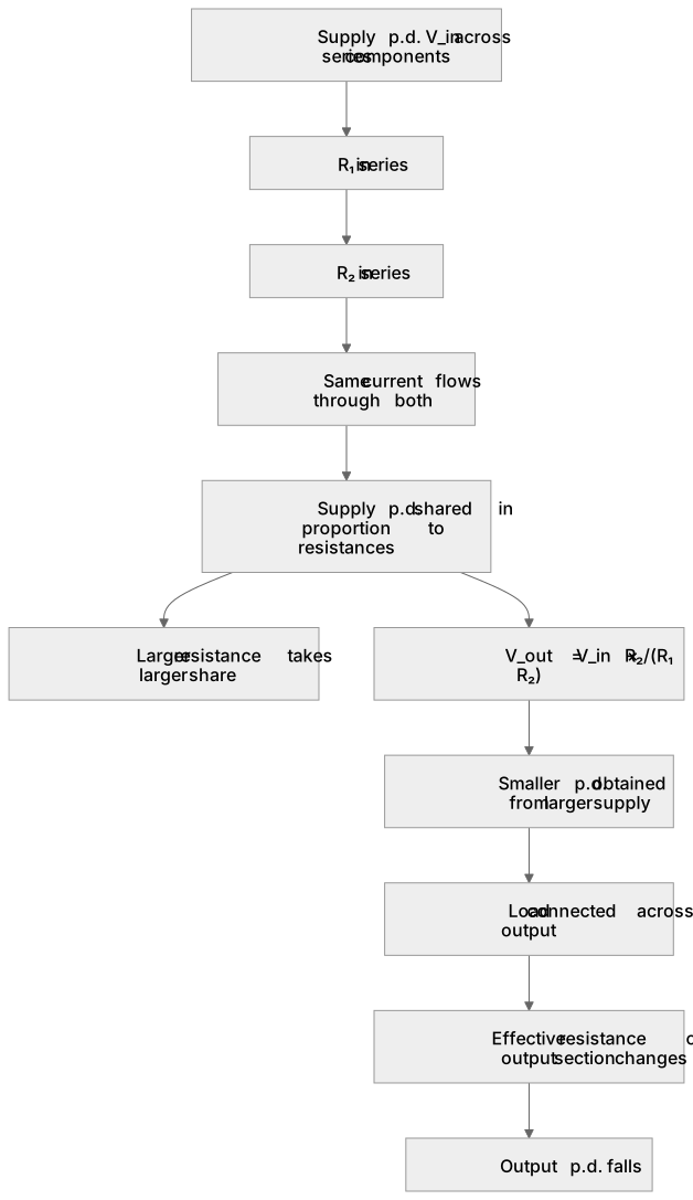
A potential divider consists of two or more components in series across a supply, so the supply p.d. is shared between them in proportion to their resistances.
Checked against the OCR H556 specification (opens in a new tab) on .
- Point 1 of 4
- 4 key terms
Study notes
From the checked teaching notes for this specification point.
The idea
A potential divider consists of two or more components in series across a supply, so the supply p.d. is shared between them in proportion to their resistances. For two resistors R₁ and R₂ in series across a supply of p.d. V_in, the p.d. across R₂ is V_out = V_in × R₂/(R₁ + R₂). The same current flows through both components, so the larger resistance takes the larger share of the p.d. Potential dividers are used to obtain a smaller p.d. from a larger supply, for example to provide a fixed reference voltage. If a load is connected across the output, the effective resistance of that part of the circuit changes and the output p.d. falls.
What earns the marks
- States that components in a potential divider are connected in series across a supply.
- Explains that the supply p.d. is divided in proportion to the resistances of the components.
- Applies V_out = V_in × R₂/(R₁ + R₂) to a two-resistor divider.
- Explains that the same current flows through each series component.
- Explains that connecting a load across the output reduces the output p.d. because the effective resistance changes.
Common mistakes and how to put them right
Assuming the p.d. divides equally regardless of resistance.
Put it right: The p.d. across each component is proportional to its resistance.
Using the ratio R₁/(R₁ + R₂) for the p.d. across R₂.
Put it right: The numerator must be the resistance across which the output is taken.
Ignoring the effect of a load.
Put it right: A load in parallel with the output reduces the effective resistance and the output p.d.
Treating the supply p.d. as the p.d. across only one component.
Put it right: The supply p.d. is shared across all series components.
Exam tips
- Identify which resistor the output is taken across before substituting into the ratio.
- Check that the two fractions for the two resistors sum to 1.
- Consider whether a connected load changes the effective resistance of the output section.
Try the lesson
The start of the Potential dividers: (a) potential divider circuit with components lesson, made from checked teaching notes for this specification point.
Listen
A potential divider consists of two or more components in series across a supply, so the supply p.d. is shared between them in proportion to their resistances. For two resistors R₁ and R₂ in series across a supply of p.d. V_in, the p.d. across R₂ is V_out = V_in × R₂/(R₁ + R₂). The same current flows through both components, so the larger resistance takes the larger share of the p.d. Potential dividers are used to obtain a smaller p.d. from a larger supply, for example to provide a fixed reference voltage. If a load is connected across the output, the effective resistance of that part of the circuit changes and the output p.d. falls. A strong answer earns marks for these points. States that components in a potential divider are connected in series across a supply. Explains that the supply p.d. is divided in proportion to the resistances of the components. Applies V_out = V_in × R₂/(R₁ + R₂) to a two-resistor divider. Explains that the same current flows through each series component. A common slip: Assuming the p.d. divides equally regardless of resistance. Instead, the p.d. across each component is proportional to its resistance. Exam tip: Identify which resistor the output is taken across before substituting into the ratio.
See it
Key words
Say what each word means before you turn the card.
Series circuits and p.d. sharing
Try answering aloud or in your head before turning the card.
Potential divider ratio
Try answering aloud or in your head before turning the card.
Effect of loading on output p.d.
Try answering aloud or in your head before turning the card.
Use of dividers to obtain smaller p.d.s
Try answering aloud or in your head before turning the card.
See every definition
- Series circuits and p.d. sharing
- A potential divider consists of two or more components in series across a supply, so the supply p.d. is shared between them in proportion to their resistances.
- Potential divider ratio
- For two resistors R₁ and R₂ in series across a supply of p.d. V_in, the p.d. across R₂ is V_out = V_in × R₂/(R₁ + R₂).
- Effect of loading on output p.d.
- If a load is connected across the output, the effective resistance of that part of the circuit changes and the output p.d. falls.
- Use of dividers to obtain smaller p.d.s
- Potential dividers are used to obtain a smaller p.d. from a larger supply, for example to provide a fixed reference voltage.
Label the diagram
Some boxes have lost their names. Pick the right name for each number.
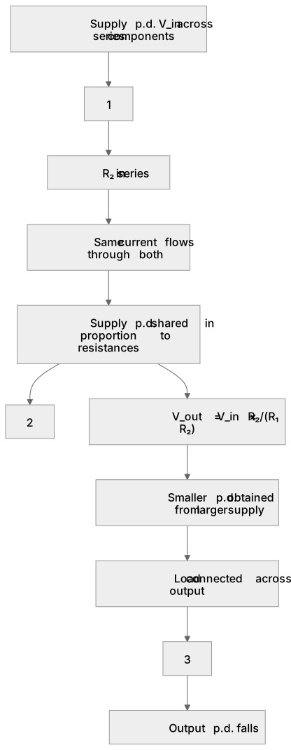
1Box 1
2Box 2
3Box 3
There is more to this lesson
The full lesson goes on to check your understanding and help you earn the marks. Create a free account to carry on, with your progress saved.
A week of Premium from your first lesson · Then the free plan continues · No card, no charge
Test your understanding of Potential dividers: (a) potential divider circuit with components
Active recall beats re-reading. Take an instant quiz now to test what you’ve learned and lock it into long-term memory.
A week of Premium from your first lesson · Then the free plan continues · No card, no charge