OCR · GCSE · Physics
Ohm's Law
This comprehensive study guide for OCR GCSE Physics (3.4) demystifies Ohm's Law, covering the crucial V=IR relationship, I-V characteristics, and the essential PAG P3 practical. It's packed with examiner insights and multi-modal resources to help you secure every available mark.
- 6 min read
- 3 worked examples
- 5 practice questions
- 6 key terms
Study Notes
Overview
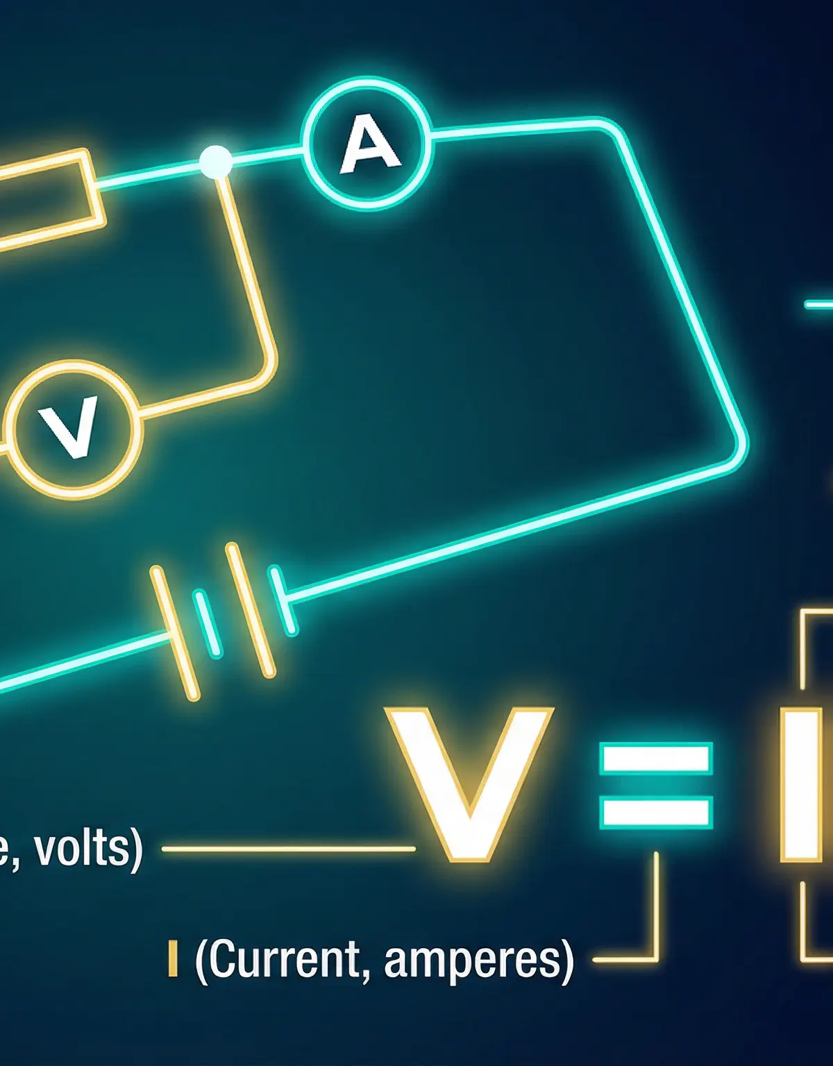
Ohm's Law is a foundational concept in electricity, describing the relationship between potential difference (voltage), current, and resistance. For your OCR GCSE Physics exam, a precise understanding is not just recommended; it's essential for achieving high marks. This topic is frequently tested through both mathematical problems (AO2) and questions requiring analysis of experimental data (AO3), particularly from the I-V characteristics practical (PAG P3). This guide will equip you with the knowledge to define the law accurately, apply the V=IR formula with confidence, and interpret the graphical behaviour of different electrical components. Mastering Ohm's Law is crucial as it forms the basis for understanding more complex circuits and links directly to topics like power (P=VI) and energy transfer, making it a cornerstone of the electricity module.
Key Concepts
Concept 1: Ohm's Law and Ohmic Conductors
Ohm's Law states that the current flowing through a conductor is directly proportional to the potential difference across it, provided that the temperature and other physical conditions remain constant. This is the full, mark-winning definition. The phrase 'directly proportional' is key; it means that if you double the voltage, the current also doubles. The 'constant temperature' condition is the most commonly forgotten part, and its omission will lose you a mark. A component that behaves in this way is called an Ohmic conductor. A standard fixed resistor is the classic example.
Example: If a 10 Ω resistor has a potential difference of 5 V across it, the current flowing through it will be I = V/R = 5 V / 10 Ω = 0.5 A. If we double the voltage to 10 V, the new current will be I = 10 V / 10 Ω = 1.0 A, which is double the original current.
Concept 2: Non-Ohmic Conductors
Many components do not obey Ohm's Law; their resistance changes as the current and voltage change. These are called non-Ohmic conductors. The two main examples you must know are the filament lamp and the diode.
- Filament Lamp: As current flows through a lamp's thin wire filament, it heats up. This increased temperature causes the metal ions within the filament to vibrate more vigorously. These vibrations obstruct the flow of electrons, leading to more frequent collisions. The result is an increase in resistance. Therefore, a filament lamp's resistance is not constant.
- Diode: A diode is a semiconductor component that allows current to flow easily in one direction (the 'forward' direction) but not the other (the 'reverse' direction). It has a very high resistance in the reverse direction and a low resistance in the forward direction once a certain threshold voltage (typically around 0.7 V) is exceeded.
Concept 3: I-V Characteristic Graphs
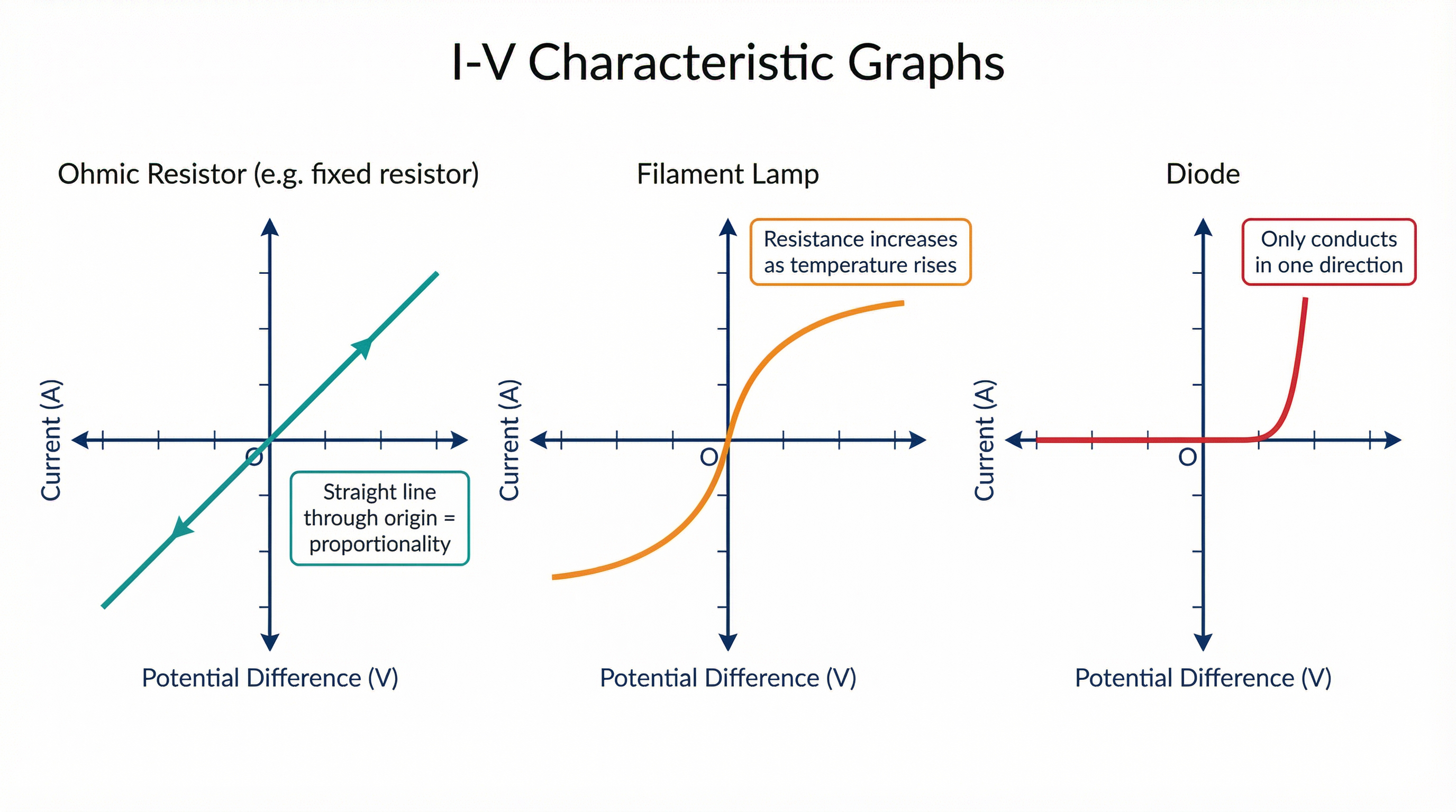
Examiners use I-V graphs to test your understanding of Ohmic and non-Ohmic behaviour. These graphs plot Current (I) on the y-axis against Potential Difference (V) on the x-axis.
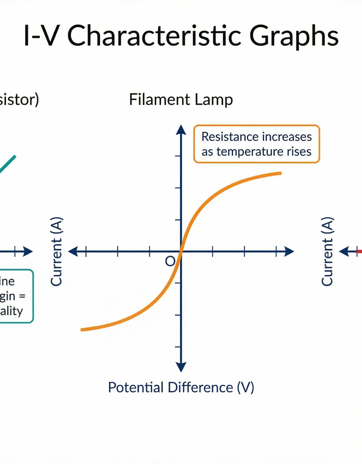
- Ohmic Conductor: The graph is a straight line passing through the origin. The constant gradient shows that I is directly proportional to V.
- Filament Lamp: The graph is a curve that starts steep and becomes shallower as voltage and current increase. This shows the resistance is increasing.
- Diode: The graph shows almost zero current for negative voltage and for positive voltage up to the threshold. After the threshold, the current rises very steeply.
Crucial Exam Point: The gradient of an I-V graph is ΔI / ΔV, which is equal to 1/R. To find the resistance (R) from an I-V graph, you must calculate 1 divided by the gradient. Do not confuse this with a V-I graph, where the gradient is R.
Mathematical/Scientific Relationships
The Ohm's Law Formula (Must memorise)
V = I × R
- V: Potential Difference, measured in Volts (V)
- I: Current, measured in Amperes (A)
- R: Resistance, measured in Ohms (Ω)
This formula can be rearranged to find any of the three variables. The 'VIR' triangle is a useful memory aid.
Unit Conversions
Examiners often provide current in milliamps (mA) or kilovolts (kV). You MUST convert these to standard units (Amps and Volts) before calculating.
- Current: 1 mA = 0.001 A (divide by 1000). Example: 250 mA = 0.25 A.
- Voltage: 1 kV = 1000 V (multiply by 1000). Example: 0.2 kV = 200 V.
Required Practical: PAG P3 - I-V Characteristics
This practical is a cornerstone of the topic and is frequently examined in 6-mark questions.
Objective: To investigate the relationship between current and potential difference for different components.
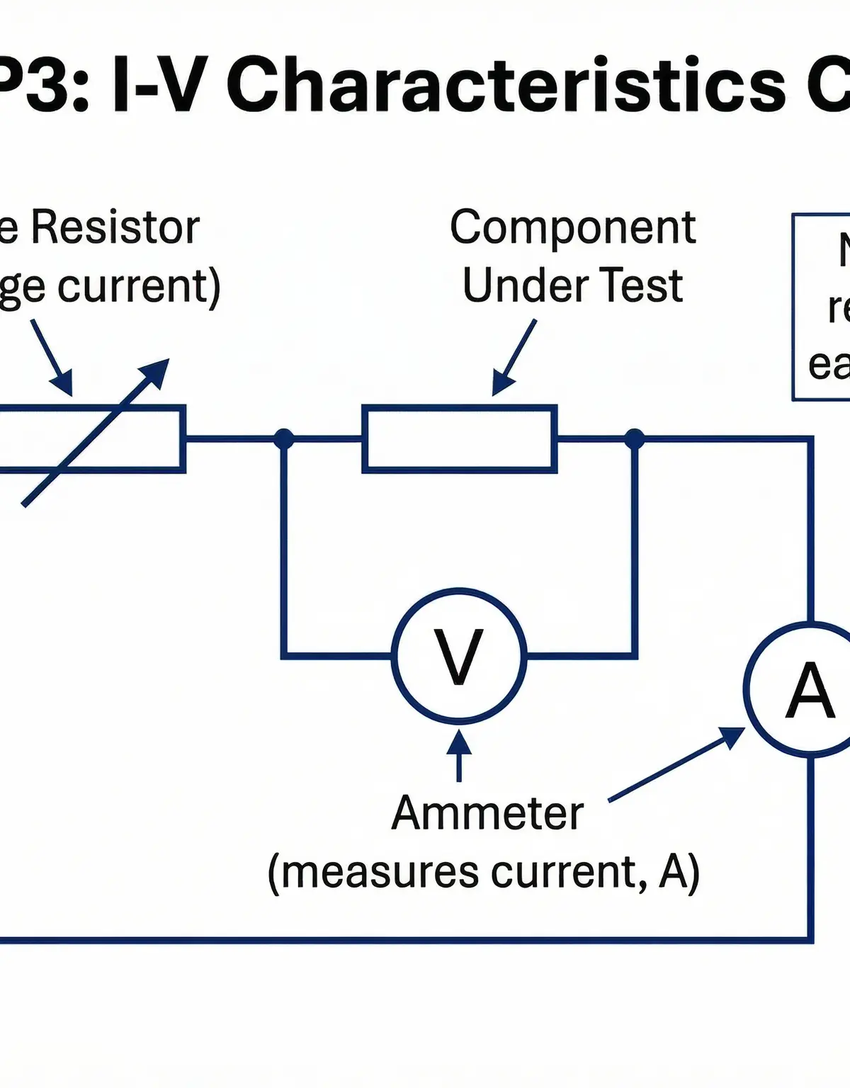
Apparatus:
- Power supply (low voltage)
- Ammeter
- Voltmeter
- Component to be tested (e.g., fixed resistor, filament lamp, diode)
- Variable resistor
- Connecting leads
Method:
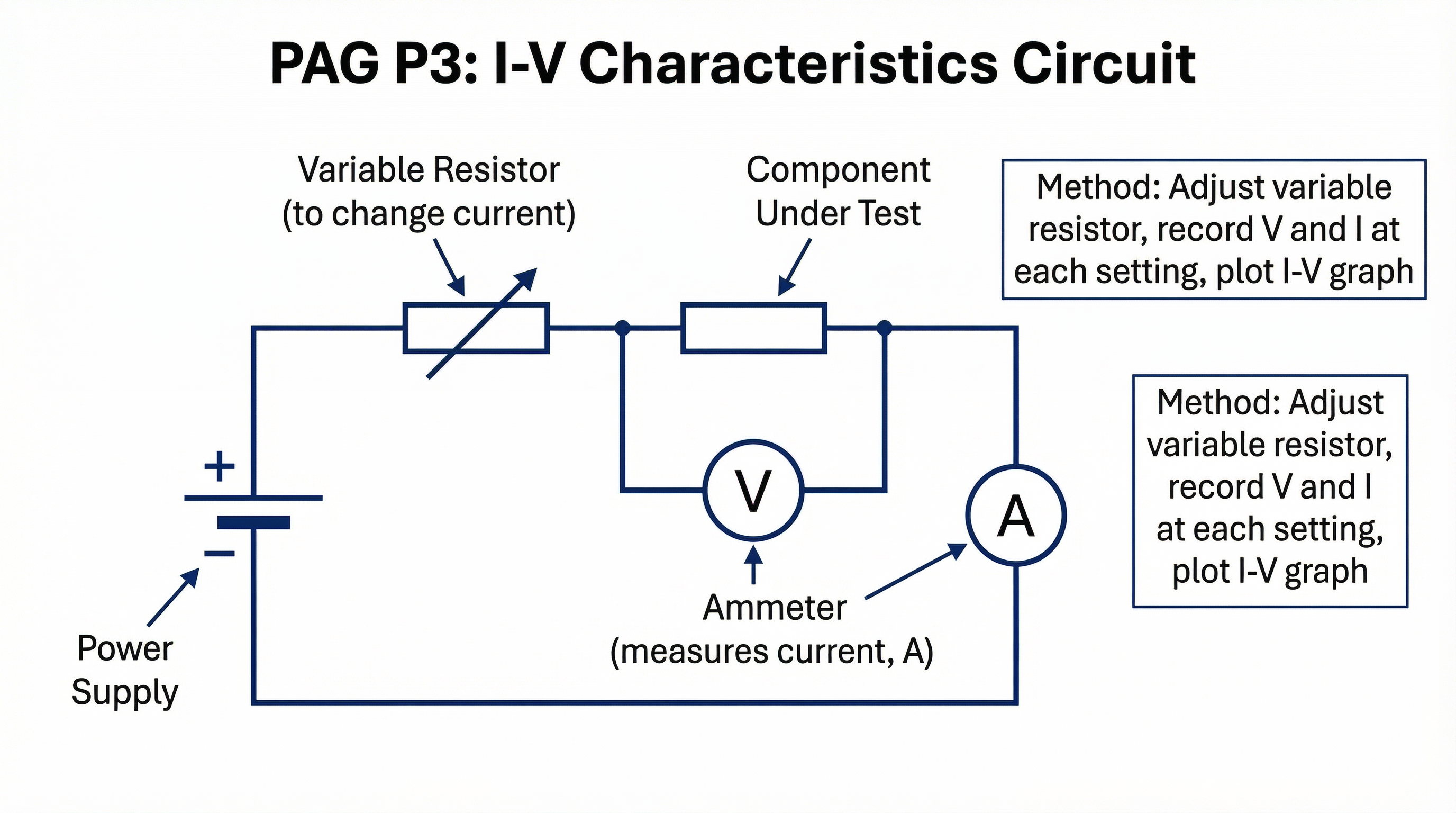
- Construct the circuit as shown in the diagram, with the ammeter in series with the component and the voltmeter in parallel across it.
- Set the variable resistor to its maximum resistance to begin.
- Switch on the power supply and record the readings on the ammeter (I) and voltmeter (V).
- Adjust the variable resistor to a new position, changing the current and voltage. Record the new I and V readings.
- Repeat this process to obtain at least 6-8 pairs of readings over a suitable range.
- For the diode, reverse the connections to the power supply to obtain readings for the reverse bias direction.
- Plot a graph of current (y-axis) against potential difference (x-axis) for each component.
Common Errors & Safety: A common error is incorrect meter placement. Remember: Ammeter in series, Voltmeter in parallel. For safety, keep the voltage low and switch off the circuit between readings to prevent the component from overheating, which would alter its resistance.
Visual Resources
4 diagrams and illustrations
Interactive Diagrams
2 interactive diagrams to visualise key concepts
Conceptual Flow Outline
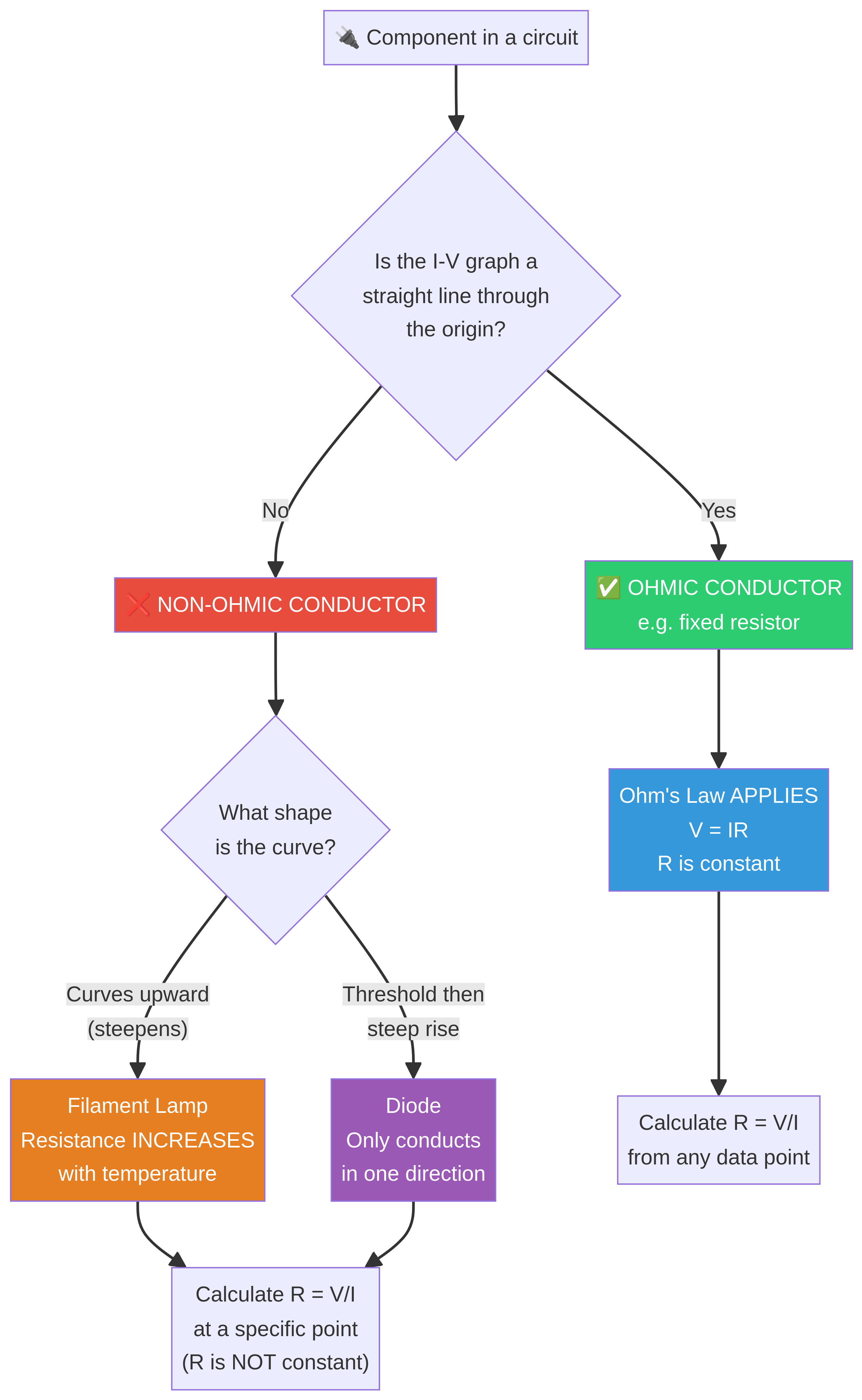
A flowchart to help decide if a component is Ohmic or non-Ohmic and how to approach calculations.
Conceptual Flow Outline
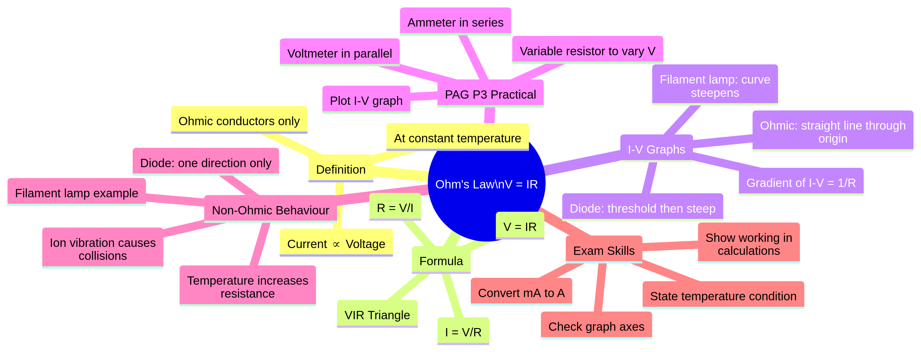
A concept map summarising the key areas of the Ohm's Law topic, from the core definition to exam skills.
Worked Examples
3 worked examples — open one to explore the question and available guidance.
Practice Questions
Test your understanding — click to reveal model answers
A resistor has a resistance of 15 Ω. Calculate the potential difference across the resistor when a current of 2.0 A flows through it. [2 marks]
Hint: Which version of the Ohm's Law formula do you need?
Compare the I-V characteristic of a fixed resistor with that of a filament lamp. [4 marks]
Hint: Think about similarities and differences. What does the shape of each graph tell you?
A student's data for an Ohmic resistor gives a V-I graph (Voltage on y-axis, Current on x-axis). The gradient of the graph is 25. What is the resistance of the resistor? Explain your answer. [2 marks]
Hint: Remember the difference between an I-V graph and a V-I graph.
A diode is connected in a circuit. The potential difference across it is 0.8 V and the current is 50 mA. It is then connected in reverse, and the potential difference is -5.0 V. Estimate the current in the reverse direction. [1 mark]
Hint: What is the key property of a diode?
Explain, in terms of particles, why the resistance of a filament lamp increases as the current through it increases. [3 marks]
Hint: Think about what current, temperature, and resistance mean at a microscopic level.
Test your understanding of Ohm's Law
Active recall beats re-reading. Take an instant quiz now to test what you’ve learned and lock it into long-term memory.
7 days Premium · Then free forever · No card, no charge