OCR · GCSE · Physics
Resistance
Master the fundamental principles of electrical resistance for your OCR GCSE Physics exam. This guide breaks down Ohm's Law, I-V characteristics, and circuit calculations into easy-to-digest sections, packed with examiner insights to help you secure top marks.
- 7 min read
- 3 worked examples
- 5 practice questions
- 6 key terms
Study Notes

Overview
Welcome to your deep dive into Resistance, a cornerstone of the OCR GCSE Physics 'Electricity' module (Specification reference: 3.3). This topic is fundamental not just for your exam, but for understanding how every electrical device works, from your phone charger to the National Grid. Examiners frequently test resistance through a combination of calculation-based questions using Ohm's Law and interpretation of graphical data. A solid grasp of the concepts here is crucial, as they form the foundation for more advanced topics like power and energy transfer. In this guide, we will deconstruct the relationship between voltage, current, and resistance, analyse the behaviour of key components like filament lamps and diodes, and master the rules for combining resistors in series and parallel circuits. Expect to see questions ranging from simple 1-mark definitions to challenging 6-mark practical design tasks, so a thorough understanding is essential for all candidates, both Foundation and Higher tier.
Key Concepts
Concept 1: Defining Resistance
In simple terms, resistance is the opposition to the flow of electric current. Imagine electrons as tiny messengers trying to run through a wire. The resistance is like a series of obstacles in their path. These obstacles are the fixed positive ions within the metal's lattice structure. As electrons flow, they collide with these ions, transferring some of their kinetic energy to them. This is why components with resistance, like a resistor or a filament lamp, heat up when current flows through them. The more collisions, the greater the opposition, and therefore, the higher the resistance.
For exam purposes, the definition that will be awarded marks is: Resistance is the ratio of the potential difference (voltage) across a component to the current flowing through it. It is measured in Ohms (Ω).
Concept 2: Ohm's Law and Ohmic Conductors
Ohm's Law is a critical principle that describes the relationship between voltage, current, and resistance for certain components. It states that for a conductor at a constant temperature, the current flowing through it is directly proportional to the potential difference across it. This means if you double the voltage, you double the current. Components that obey Ohm's Law are called ohmic conductors. A standard resistor is the classic example.
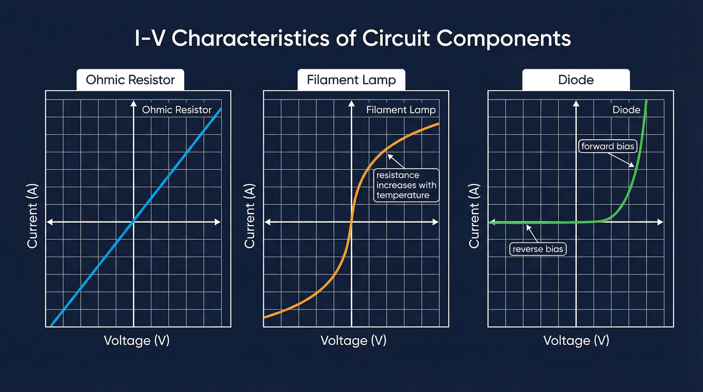
When you plot a graph of current (I) against voltage (V) for an ohmic conductor, you get a straight line that passes through the origin (0,0). The resistance is constant. It's important to note the condition: at a constant temperature. This is a key phrase examiners look for.
Concept 3: Non-Ohmic Conductors & I-V Characteristics
Many components do not obey Ohm's Law; their resistance changes as the current and voltage change. These are non-ohmic conductors. You must be able to sketch and interpret the I-V characteristic graphs for two key examples: the filament lamp and the diode.
-
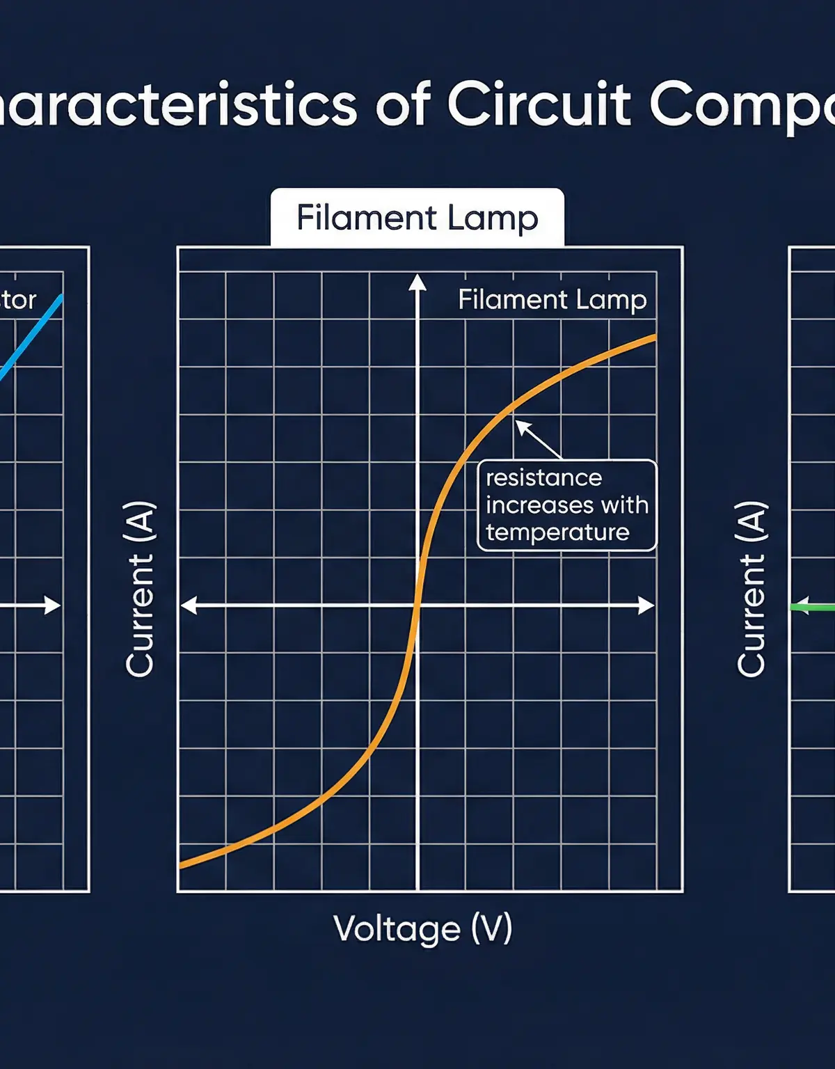
Filament Lamp: As the voltage across a filament lamp increases, the current increases, causing the thin metal filament inside to get very hot. This increased temperature causes the metal ions in the filament to vibrate more vigorously. These increased vibrations make it more difficult for the charge-carrying electrons to pass through, so the resistance of the filament increases. The I-V graph is a curve that starts steep (low resistance) and becomes progressively shallower (higher resistance) as the voltage and current increase. Credit is given for explaining that the increased lattice ion vibrations impede electron flow.
-
Diode: A diode is a semiconductor component that allows current to flow in only one direction. In the forward bias direction, once the voltage reaches a certain threshold (typically around 0.6-0.7V), the resistance becomes very low, and current flows easily. In the reverse bias direction, the resistance is extremely high, and almost no current can flow. The I-V graph shows virtually zero current for all negative voltages and then a sharp, almost vertical increase in current once the forward threshold voltage is exceeded.
Concept 4: Series and Parallel Circuits
How you connect resistors in a circuit has a major impact on the total resistance. You need to be able to calculate the total resistance for both series and parallel arrangements.

-
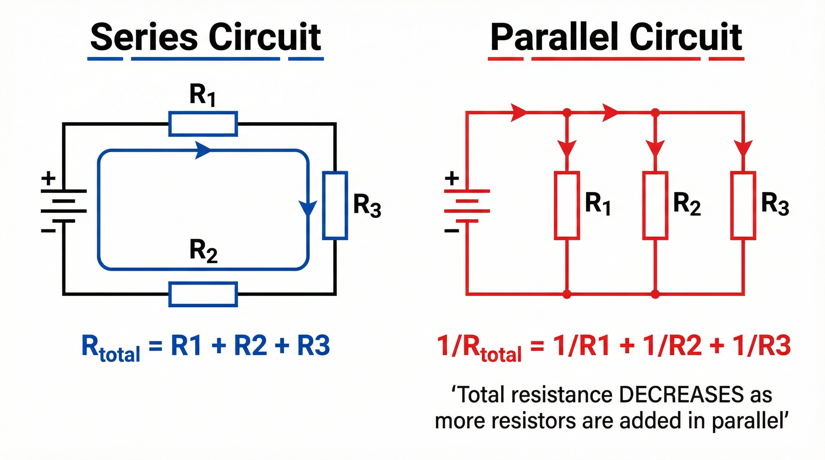
Series Circuits: When resistors are connected in series, they are in a single, unbroken loop. The current has only one path to take. The total resistance is found by simply adding up the individual resistances. This is because the current has to flow through every resistor, so their oppositions combine.
-
Parallel Circuits: When resistors are connected in parallel, they are on separate branches of the circuit. The current splits, with some flowing down each branch. This provides multiple paths for the current, which makes it easier for charge to flow overall. Consequently, the total resistance of a parallel circuit is always less than the resistance of the smallest individual resistor. This is a common point of confusion, but a crucial one to remember. Adding more resistors in parallel decreases the total resistance.
Mathematical/Scientific Relationships
-
Ohm's Law Formula (Must memorise)
R = V / I
Where:R= Resistance (in Ohms, Ω)V= Potential Difference (in Volts, V)I= Current (in Amperes, A)
This can be rearranged toV = I × RorI = V / R. TheV=IRform is most commonly used in calculations.
-
Total Resistance in Series (Must memorise)
R_total = R₁ + R₂ + R₃ + ...
You simply sum the values of all resistors in the series loop. -
Total Resistance in Parallel (Given on formula sheet for Higher Tier)
1/R_total = 1/R₁ + 1/R₂ + 1/R₃ + ...
To findR_total, you must calculate the value of the right-hand side and then take the reciprocal (1 divided by your answer).
Practical Applications
Required Practical: Investigating Resistance
OCR requires candidates to be familiar with Practical Activity Group (PAG) investigations. For resistance, this involves investigating the factors that affect the resistance of a wire.
- Apparatus: Power pack, ammeter, voltmeter, length of resistance wire (e.g., nichrome) attached to a metre ruler, connecting leads, crocodile clips.
- Method to Investigate Length:
- Set up the circuit with the ammeter in series and the voltmeter in parallel across the resistance wire.
- Attach one crocodile clip to the wire at 0 cm. Attach the second clip at 10 cm.
- Record the voltage (V) from the voltmeter and the current (I) from the ammeter.
- Calculate the resistance using R = V/I.
- Move the second crocodile clip to 20 cm, 30 cm, 40 cm, etc., up to 100 cm, repeating the readings and calculation at each length.
- Expected Results: As the length of the wire increases, the resistance should increase proportionally. A graph of Resistance vs. Length should be a straight line through the origin.
- Control Variables: To ensure a fair test, you must keep other factors constant. For a 6-mark question, you must be specific: the material of the wire, the cross-sectional area (thickness) of the wire, and the temperature of the wire.
- Common Errors: Parallax error when reading the ruler or meters. The wire heating up during the experiment (which increases its resistance); to minimise this, use a low voltage or switch the current off between readings.
Visual Resources
2 diagrams and illustrations
Interactive Diagrams
2 interactive diagrams to visualise key concepts
Conceptual Flow Outline
Flowchart showing the experimental method for investigating how the length of a wire affects its resistance.
Conceptual Flow Outline
Concept map illustrating the classification of components based on their resistance characteristics.
Worked Examples
3 worked examples — open one to explore the question and available guidance.
Practice Questions
Test your understanding — click to reveal model answers
State the equation that links potential difference, current and resistance.
A resistor has a potential difference of 6.0V across it and a current of 200 mA flowing through it. Calculate the resistance of the resistor.
Hint: Remember to convert the current to the standard unit (Amperes) before you calculate.
Explain why adding another resistor in parallel with an existing resistor decreases the total resistance of the circuit.
Compare the I-V characteristics of an ohmic conductor and a semiconductor diode.
A student investigates how the resistance of a wire depends on its length. Describe a suitable method for this investigation. Your answer should include any control variables.
Test your understanding of Resistance
Active recall beats re-reading. Take an instant quiz now to test what you’ve learned and lock it into long-term memory.
7 days Premium · Then free forever · No card, no charge