AQA · A-Level · Physics
Course version: 7408 · Version from Sept 2016
Modulo- n counter from basic counter with the logic driving a reset pin.
Full specification wording
Sequential logic (A-level only): Modulo- n counter from basic counter with the logic driving a reset pin.
A modulo-n counter counts from 0 up to n − 1 and then resets to 0, so it has n distinct states.
Checked against the AQA 7408 specification (opens in a new tab) on .
- Point 4 of 5
- 4 key terms
Study notes
From the checked teaching notes for this specification point.
The idea
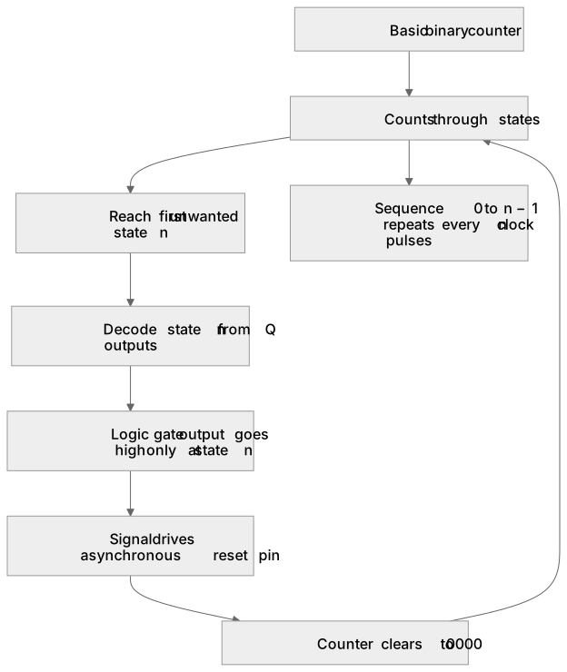
A modulo-n counter counts from 0 up to n − 1 and then resets to 0, so it has n distinct states. You build one from a basic binary counter by decoding the first unwanted state and feeding that decoded signal to the counter's reset pin. For example, a modulo-6 counter using a 4-bit binary counter must reset when the count reaches 6, which is 0110 in binary. A logic gate combines the appropriate Q outputs so that its output goes high only at that state; that signal drives the asynchronous reset, clearing the counter to 0000. The decoded state may appear briefly, so the reset pulse must be short and the gate must respond to the correct combination of outputs. The result is a counter whose sequence repeats every n clock pulses.
What earns the marks
- State the number of distinct states n and the binary value of the first unwanted state, which is n itself.
- Select the counter outputs that are high in that unwanted state and combine them with a logic gate to produce the reset signal.
- Connect the decoded signal to the reset pin so the counter clears to zero when the unwanted state is reached.
- Describe the repeating sequence of states from 0 to n − 1 and back to 0.
- Explain that the reset is usually asynchronous, so the counter may clear before the next clock edge.
- Check that the decoding gate produces a high output only for the unwanted state and not for any valid state.
Common mistakes and how to put them right
Decoding the state n − 1 instead of n.
Put it right: Reset on the first state that must not appear, which is n.
Using an AND gate when the required outputs are not all high.
Put it right: Choose the gate that matches the polarity of the outputs being decoded.
Forgetting that the reset clears the counter to zero rather than to one.
Put it right: State the reset state explicitly.
Assuming the decoded state is stable for a full clock period.
Put it right: Note that asynchronous reset may clear the counter almost immediately.
Exam tips
- Write the binary value of n before choosing which outputs to decode.
- State clearly which outputs feed the gate and what the gate output does.
- Describe the full repeating sequence so the modulo behaviour is unambiguous.
- Mention that the reset is asynchronous if the circuit uses an asynchronous reset pin.
Try the lesson
The start of the Sequential logic (A-level only): Modulo- n counter from basic counter with the logic driving a reset pin. lesson, made from checked teaching notes for this specification point.
Have a go first
A modulo-6 counter is built from a basic binary counter by feeding a logic gate into the reset pin. How many different output states does the counter pass through before it resets?
Listen
A modulo-n counter counts from 0 up to n − 1 and then resets to 0, so it has n distinct states. You build one from a basic binary counter by decoding the first unwanted state and feeding that decoded signal to the counter's reset pin. For example, a modulo-6 counter using a 4-bit binary counter must reset when the count reaches 6, which is 0110 in binary. A logic gate combines the appropriate Q outputs so that its output goes high only at that state; that signal drives the asynchronous reset, clearing the counter to 0000. The decoded state may appear briefly, so the reset pulse must be short and the gate must respond to the correct combination of outputs. The result is a counter whose sequence repeats every n clock pulses. A strong answer earns marks for these points. State the number of distinct states n and the binary value of the first unwanted state, which is n itself. Select the counter outputs that are high in that unwanted state and combine them with a logic gate to produce the reset signal. Connect the decoded signal to the reset pin so the counter clears to zero when the unwanted state is reached. Describe the repeating sequence of states from 0 to n − 1 and back to 0. A common slip: Decoding the state n − 1 instead of n. Instead, reset on the first state that must not appear, which is n. Exam tip: Write the binary value of n before choosing which outputs to decode.
See it
Key words
Say what each word means before you turn the card.
Modulo-n counter
Try answering aloud or in your head before turning the card.
Reset pin
Try answering aloud or in your head before turning the card.
Asynchronous reset
Try answering aloud or in your head before turning the card.
Decoding gate
Try answering aloud or in your head before turning the card.
See every definition
- Modulo-n counter
- Counts from 0 up to n − 1 and then resets to 0, so it has n distinct states.
- Reset pin
- The input that clears the counter to zero when the decoded signal reaches it.
- Asynchronous reset
- A reset that may clear the counter before the next clock edge, so the decoded state may appear only briefly.
- Decoding gate
- A logic gate that combines the appropriate Q outputs so its output goes high only at the unwanted state.
Label the diagram
Some boxes have lost their names. Pick the right name for each number.
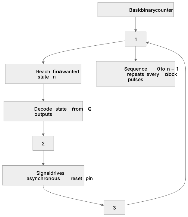
1Box 1
2Box 2
3Box 3
There is more to this lesson
The full lesson goes on to check your understanding and help you earn the marks. Create a free account to carry on, with your progress saved.
A week of Premium from your first lesson · Then the free plan continues · No card, no charge
Test your understanding of Sequential logic (A-level only): Modulo- n counter from basic counter with the logic driving a reset pin.
Active recall beats re-reading. Take an instant quiz now to test what you’ve learned and lock it into long-term memory.
A week of Premium from your first lesson · Then the free plan continues · No card, no charge