OCR · GCSE · Physics
Course version: J249 · Version from Sept 2018
Use of appropriate apparatus to measure current, potential difference…
Full specification wording
Circuit components: Use of appropriate apparatus to measure current, potential difference (voltage) and resistance, and to explore the characteristics of a variety of circuit elements.
This practical statement asks you to build circuits and use meters correctly to measure current, potential difference and resistance, then to investigate how different circuit elements behave.
Checked against the OCR J249 specification (opens in a new tab) on .
- 4 key terms
Study notes
From the checked teaching notes for this specification point.
The idea
This practical statement asks you to build circuits and use meters correctly to measure current, potential difference and resistance, then to investigate how different circuit elements behave. An ammeter goes in series with the component so the same current flows through it, while a voltmeter goes in parallel across the component. You can obtain resistance from the potential difference across a component divided by the current through it, R = V ÷ I, with V in volts, I in amperes and R in ohms. To explore characteristics you vary the current or potential difference and record pairs of readings, then plot a graph of current against potential difference. A filament lamp curves because its resistance rises as it heats, a fixed resistor gives a straight line through the origin, and a diode conducts mainly in one direction.
What earns the marks
- Places the ammeter in series with the component and the voltmeter in parallel across it so each meter measures the intended quantity.
- Connects the circuit safely, checking polarity and keeping the current within the rating of the components and meters.
- Calculates resistance from potential difference divided by current and states the unit as the ohm.
- Varies the potential difference or current to collect several paired readings and plots a graph to identify the characteristic of the element.
- Interprets the shape of the characteristic, for example recognising that a filament lamp's resistance increases as it heats.
Common mistakes and how to put them right
Connects the ammeter in parallel with the component.
Put it right: Place the ammeter in series so the current passes through it.
Connects the voltmeter in series.
Put it right: Place the voltmeter in parallel across the component being tested.
Assumes every element gives a straight-line graph.
Put it right: Compare the shapes and link curvature to changing resistance with temperature.
Exam tips
- State the position of each meter relative to the component before describing the readings.
- Show the resistance calculation with the values substituted and give the answer in ohms.
- Describe how you change the independent variable and what you keep constant when collecting a set of readings.
Try the lesson
The start of the Circuit components: Use of appropriate apparatus to measure current, potential difference (voltage) and resistance, and to explore the characteristics of a variety of circuit elements. lesson, made from checked teaching notes for this specification point.
Have a go first
A student wants to measure the current flowing through a filament lamp in a circuit. How should an ammeter be connected?
Listen
This practical statement asks you to build circuits and use meters correctly to measure current, potential difference and resistance, then to investigate how different circuit elements behave. An ammeter goes in series with the component so the same current flows through it, while a voltmeter goes in parallel across the component. You can obtain resistance from the potential difference across a component divided by the current through it, R = V ÷ I, with V in volts, I in amperes and R in ohms. To explore characteristics you vary the current or potential difference and record pairs of readings, then plot a graph of current against potential difference. A filament lamp curves because its resistance rises as it heats, a fixed resistor gives a straight line through the origin, and a diode conducts mainly in one direction. A strong answer earns marks for these points. Places the ammeter in series with the component and the voltmeter in parallel across it so each meter measures the intended quantity. Connects the circuit safely, checking polarity and keeping the current within the rating of the components and meters. Calculates resistance from potential difference divided by current and states the unit as the ohm. Varies the potential difference or current to collect several paired readings and plots a graph to identify the characteristic of the element. Exam tip: State the position of each meter relative to the component before describing the readings.
See it
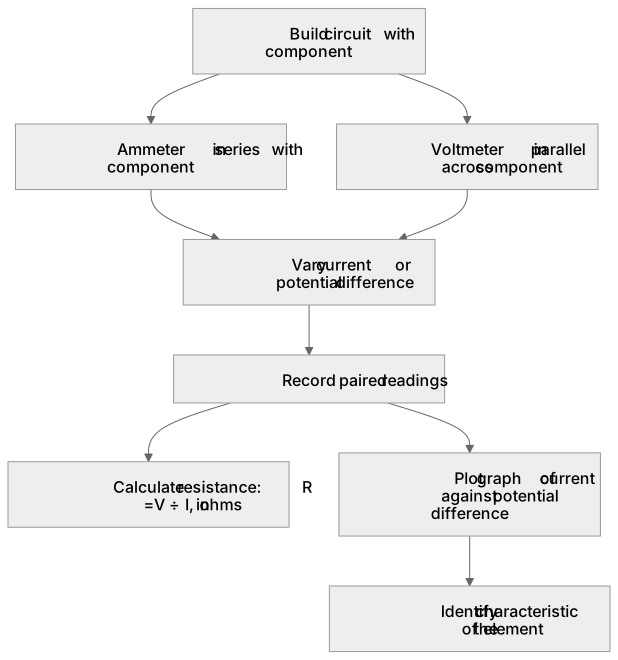
Key words
Say what each word means before you turn the card.
Ammeter
Try answering aloud or in your head before turning the card.
Voltmeter
Try answering aloud or in your head before turning the card.
Resistance
Try answering aloud or in your head before turning the card.
Characteristic
Try answering aloud or in your head before turning the card.
See every definition
- Ammeter
- Goes in series with the component so the same current flows through it.
- Voltmeter
- Goes in parallel across the component being tested.
- Resistance
- Obtained from the potential difference across a component divided by the current through it, with the unit stated as the ohm.
- Characteristic
- Identified by varying the current or potential difference, recording pairs of readings and plotting a graph of current against potential difference.
Label the diagram
Some boxes have lost their names. Pick the right name for each number.
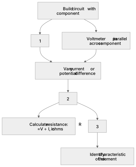
1Box 1
2Box 2
3Box 3
There is more to this lesson
The full lesson goes on to check your understanding and help you earn the marks. Create a free account to carry on, with your progress saved.
A week of Premium from your first lesson · Then the free plan continues · No card, no charge
Test your understanding of Circuit components: Use of appropriate apparatus to measure current, potential difference (voltage) and resistance, and to explore the characteristics of a variety of circuit elements.
Active recall beats re-reading. Take an instant quiz now to test what you’ve learned and lock it into long-term memory.
A week of Premium from your first lesson · Then the free plan continues · No card, no charge