AQA · GCSE · Physics
Course version: 8463 · Version from Sept 2016
Students should be able to: explain the design and use of a circuit to…
Full specification wording
Resistors: Students should be able to: explain the design and use of a circuit to measure the resistance of a component by measuring the current through, and potential difference across, the component draw an appropriate circuit diagram using correct circuit symbols.
To measure the resistance of a component you need three readings and one equation.
Checked against the AQA 8463 specification (opens in a new tab) on .
- Point 11 of 13
- 4 key terms
Study notes
From the checked teaching notes for this specification point.
The idea
To measure the resistance of a component you need three readings and one equation. Connect the component in series with a cell or battery, an ammeter and a variable resistor, and connect a voltmeter in parallel across the component alone. The ammeter is in series so the current it reads is the current through the component; the voltmeter is in parallel so the potential difference it reads is the one across the component. Adjust the variable resistor, or change the number of cells or the supply setting, to get several pairs of readings, then calculate R = V ÷ I for each and take a mean. Draw the circuit with standard symbols, straight lines and a dot at each junction.
What earns the marks
- The cell or battery in series with the component and the ammeter.
- The voltmeter connected in parallel across the component being tested.
- A way of varying the potential difference, such as a variable resistor or changing the number of cells.
- Calculating resistance as potential difference divided by current and giving the unit as ohms.
Common mistakes and how to put them right
Connecting the voltmeter across the battery, so it reads the supply rather than the component.
Putting the ammeter in parallel with the component, which short circuits it.
Taking a single pair of readings, leaving no mean and no check on the value.
Drawing non-standard symbols that the examiner cannot identify.
Exam tips
- Say aloud as you draw: ammeter in series, voltmeter across the component only.
- Include a variable resistor in every design of this kind; it is regularly a mark of its own.
- State the equation you will use at the end of a method answer, with its unit.
Try the lesson
The start of the Resistors: Students should be able to: explain the design and use of a circuit to measure the resistance of a component by measuring the current through, and potential difference across, the component draw an appropriate circuit diagram using correct circuit symbols. lesson, made from checked teaching notes for this specification point.
Have a go first
A student is designing a circuit to determine the resistance of a component. Which combination of meters and connections is required to take the correct measurements?
Listen
To measure the resistance of a component you need three readings and one equation. Connect the component in series with a cell or battery, an ammeter and a variable resistor, and connect a voltmeter in parallel across the component alone. The ammeter is in series so the current it reads is the current through the component; the voltmeter is in parallel so the potential difference it reads is the one across the component. Adjust the variable resistor, or change the number of cells or the supply setting, to get several pairs of readings, then calculate R = V ÷ I for each and take a mean. Draw the circuit with standard symbols, straight lines and a dot at each junction. A strong answer earns marks for these points. the cell or battery in series with the component and the ammeter. the voltmeter connected in parallel across the component being tested. a way of varying the potential difference, such as a variable resistor or changing the number of cells. calculating resistance as potential difference divided by current and giving the unit as ohms. Exam tip: Say aloud as you draw: ammeter in series, voltmeter across the component only.
See it
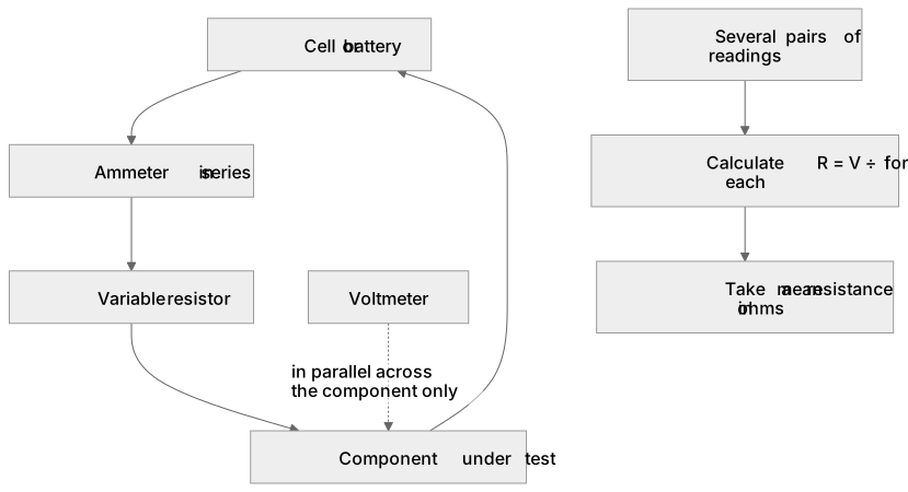
Key words
Say what each word means before you turn the card.
ammeter in series
Try answering aloud or in your head before turning the card.
voltmeter in parallel
Try answering aloud or in your head before turning the card.
varying the potential difference
Try answering aloud or in your head before turning the card.
standard circuit symbols
Try answering aloud or in your head before turning the card.
See every definition
- ammeter in series
- The ammeter is connected in series so the current it reads is the current through the component.
- voltmeter in parallel
- The voltmeter is connected in parallel across the component alone, so the potential difference it reads is the one across the component.
- varying the potential difference
- Adjust the variable resistor, or change the number of cells or the supply setting, to get several pairs of readings.
- standard circuit symbols
- The circuit is drawn with standard symbols, straight lines and a dot at each junction.
Label the diagram
Some boxes have lost their names. Pick the right name for each number.
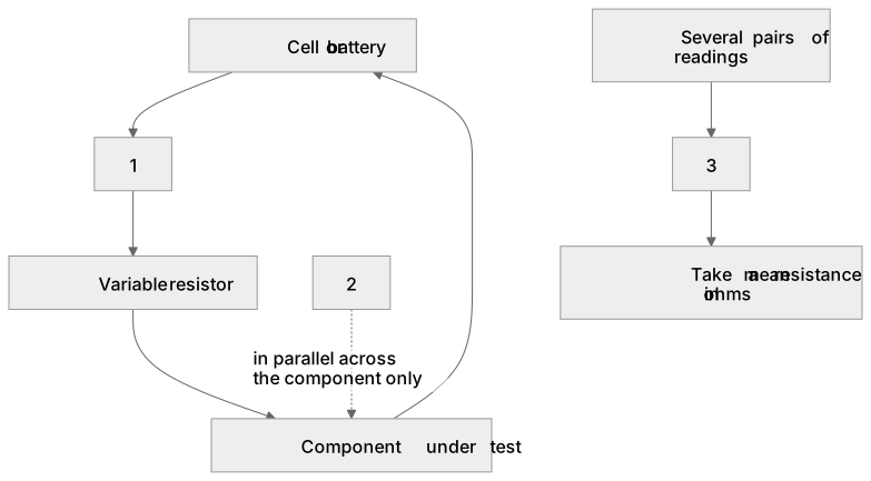
1Box 1
2Box 2
3Box 3
There is more to this lesson
The full lesson goes on to check your understanding and help you earn the marks. Create a free account to carry on, with your progress saved.
A week of Premium from your first lesson · Then the free plan continues · No card, no charge
Test your understanding of Resistors: Students should be able to: explain the design and use of a circuit to measure the resistance of a component by measuring the current through, and potential difference across, the component draw an appropriate circuit diagram using correct circuit symbols.
Active recall beats re-reading. Take an instant quiz now to test what you’ve learned and lock it into long-term memory.
A week of Premium from your first lesson · Then the free plan continues · No card, no charge