
Study Notes
Overview
Welcome to the study of Electricity, a fundamental and heavily-weighted topic within the WJEC GCSE Combined Science specification. This area of physics governs everything from the smartphone in your pocket to the national grid powering your home. For your exam, a thorough understanding is essential, as it forms the basis for a significant portion of the questions you will face. Examiners assess this topic through a combination of circuit analysis, quantitative problem-solving using key formulas, and your understanding of the required practical investigations. This guide will break down the core concepts, from the simple rules of series and parallel circuits to the complexities of I-V characteristics and the vital safety features in domestic wiring. Expect to see questions that require you to draw and interpret circuit diagrams, calculate power and energy, and explain the behaviour of different electrical components. Strong synoptic links can be made to topics like 'Energy' (through power and energy transfer) and 'Waves' (when considering alternating current), and examiners often reward candidates who can make these connections.
Key Concepts
Concept 1: Electric Circuits, Symbols, and Current
An electric circuit is a closed loop or path that allows electric charge (in the form of electrons) to flow. For a current to flow, there must be a source of potential difference, such as a battery or power supply, and the circuit must be complete. We use standard symbols to represent components in circuit diagrams, and it is vital you memorise these. The flow of charge is called the electric current (I), measured in amperes (A). Conventionally, we think of current flowing from the positive terminal of a power source to the negative terminal (conventional current), although the electrons themselves flow in the opposite direction.
Example: In a simple circuit with a 6V battery and a bulb, a current of 2A means that 2 Coulombs of charge pass any point in the circuit every second.
Concept 2: Potential Difference and Resistance
Potential difference (V), also known as voltage, is the work done per unit of charge. It is the 'push' that drives the current around the circuit and is measured in volts (V). A voltmeter is used to measure potential difference and is always connected in parallel across the component being measured. Resistance (R) is a measure of how much a component opposes the flow of current, measured in ohms (Ω). A higher resistance means a lower current for the same potential difference.
Example: If a 12V battery produces a current of 3A through a resistor, the resistance of that resistor is R = V/I = 12V / 3A = 4Ω.
Concept 3: Series and Parallel Circuits
Components in a circuit can be connected in series or in parallel, and the rules governing them are different and a frequent source of exam questions.
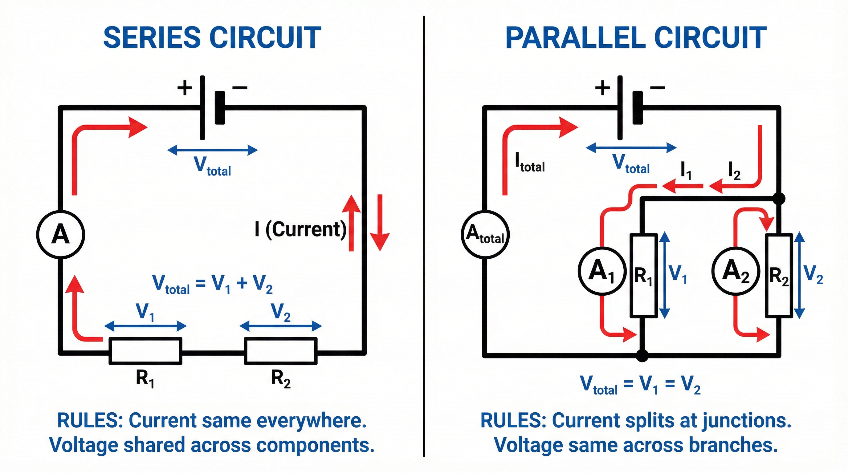
Series Circuits
- Components are connected end-to-end in a single loop.
- Current: The current is the same at all points in the circuit (I_total = I_1 = I_2 = ...).
- Potential Difference: The total potential difference from the source is shared between the components (V_total = V_1 + V_2 + ...).
- Resistance: The total resistance is the sum of the individual resistances (R_total = R_1 + R_2 + ...).
Parallel Circuits
- Components are connected on separate branches.
- Current: The total current from the source splits at the junctions and recombines before returning to the source. The total current is the sum of the currents in each branch (I_total = I_1 + I_2 + ...).
- Potential Difference: The potential difference is the same across all branches (V_total = V_1 = V_2 = ...).
- Resistance: The total resistance of two resistors in parallel is less than the resistance of the smallest individual resistor. The formula (Higher Tier only) is 1/R_total = 1/R_1 + 1/R_2.
Concept 4: I-V Characteristics
The relationship between current and voltage for a component is shown by its I-V characteristic graph. This is a key part of the required practical.
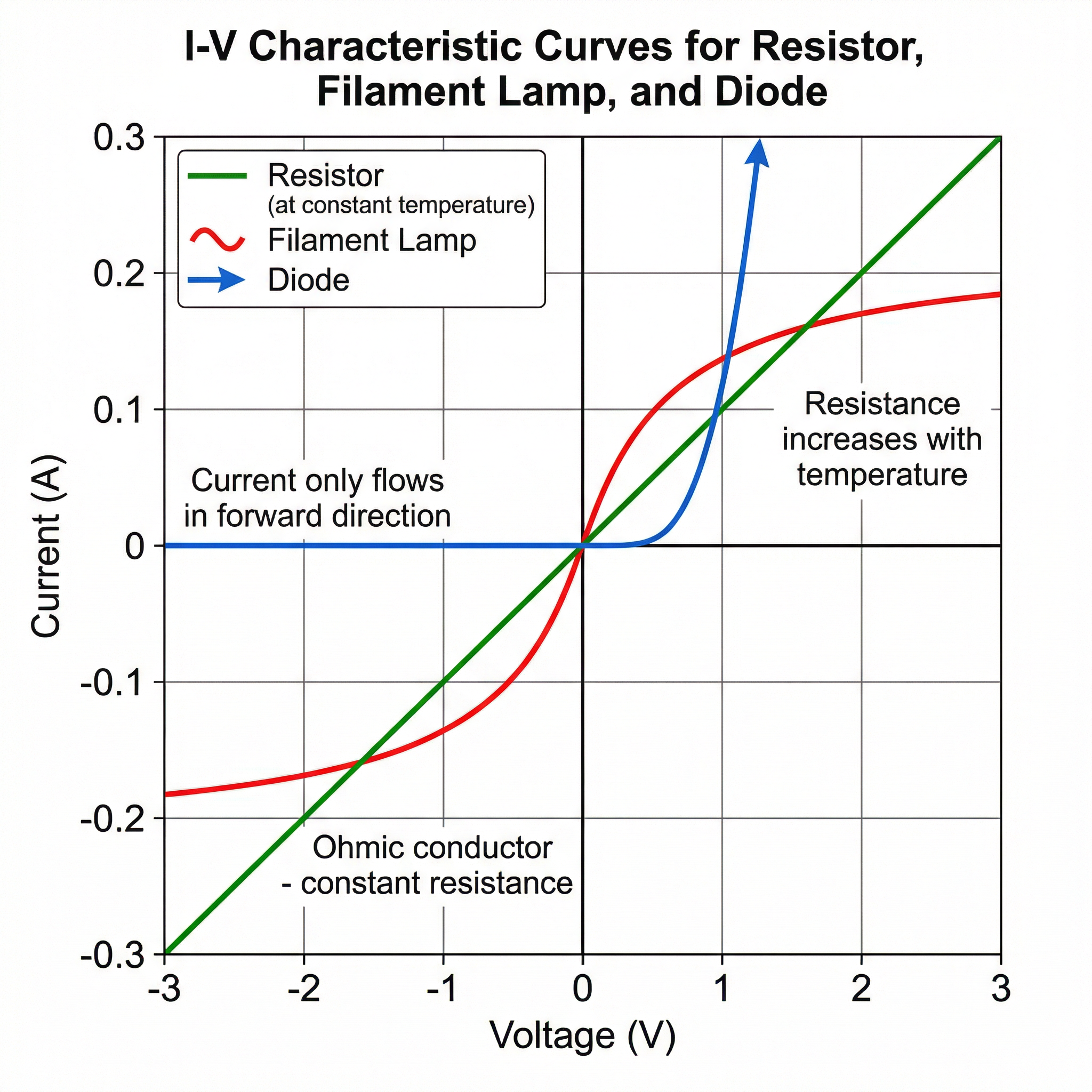
- Ohmic Conductor (e.g., a resistor at constant temperature): The current is directly proportional to the potential difference. The I-V graph is a straight line through the origin. Resistance is constant.
- Filament Lamp: The graph is an S-shaped curve. As the voltage increases, the current increases, but the filament gets hotter. This increases the vibrations of the metal ions in the filament, which impedes the flow of electrons, so the resistance increases. Credit is given for explaining this temperature effect.
- Diode: A diode allows current to flow easily in one direction (the forward direction) but has a very high resistance in the opposite direction (the reverse direction). The graph is flat on the negative voltage axis and then rises steeply on the positive voltage axis after a certain threshold voltage.
Concept 5: Electrical Power and Energy
Power (P) is the rate at which energy is transferred. It is measured in watts (W). One watt is one joule per second.
Energy (E) transferred is calculated based on the power of the appliance and how long it is used for. It is measured in joules (J) or, for domestic electricity bills, kilowatt-hours (kWh).
Concept 6: Domestic Electricity and Safety
UK mains electricity is an alternating current (AC) supply at approximately 230V and a frequency of 50Hz. It is crucial to understand the safety features designed to protect both users and appliances.
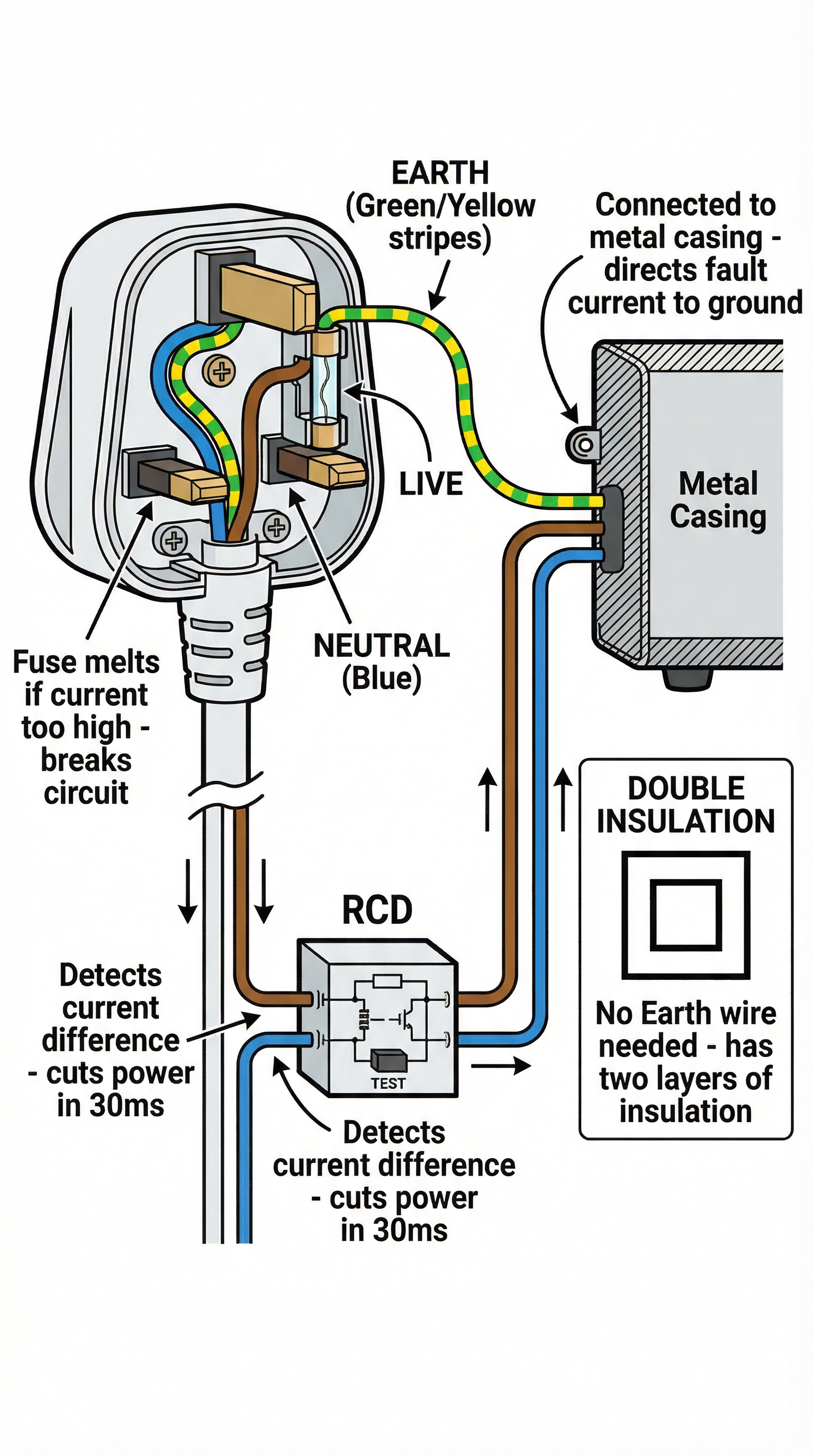
- Wiring: Plugs contain three wires: Live (brown), Neutral (blue), and Earth (green and yellow stripes). The live wire carries the high potential, the neutral wire completes the circuit (at or near 0V), and the earth wire is a safety feature.
- Fuses and Circuit Breakers: These are placed in the live wire. A fuse contains a thin wire designed to melt and break the circuit if the current gets too high. A circuit breaker is an automatic switch that does the same job but can be reset. They protect the appliance, not the person.
- Earthing: The earth wire connects the metal casing of an appliance to the ground. If a fault causes the live wire to touch the metal case, a very large current flows to the earth, blowing the fuse or tripping the circuit breaker and disconnecting the supply. This prevents the casing from becoming live and giving an electric shock.
- Double Insulation: Some appliances do not need an earth wire. They have plastic casings or have been designed with two layers of insulation. These are marked with a symbol of a square inside another square.
Mathematical/Scientific Relationships
Here are the key formulas you need to know for the Electricity topic. Ensure you can recall and apply them correctly.
| Formula | Symbol Meanings | Given or Memorise? |
|---|---|---|
V = I × R | V = Potential Difference (V), I = Current (A), R = Resistance (Ω) | Must memorise |
P = I × V | P = Power (W), I = Current (A), V = Potential Difference (V) | Must memorise |
P = I² × R | P = Power (W), I = Current (A), R = Resistance (Ω) | Given on formula sheet |
P = V² / R | P = Power (W), V = Potential Difference (V), R = Resistance (Ω) | Given on formula sheet |
E = P × t | E = Energy (J), P = Power (W), t = time (s) | Must memorise |
E = Q × V | E = Energy (J), Q = Charge (C), V = Potential Difference (V) | Must memorise |
Q = I × t | Q = Charge (C), I = Current (A), t = time (s) | Must memorise |
Cost = Power (kW) × time (h) × cost per kWh | Used for calculating electricity bills | Must memorise concept |
Required Practical: Investigating I-V Characteristics
This is a compulsory practical, and examiners can ask you to describe the method, draw the circuit, analyse results, or identify sources of error.
Apparatus List:
- Power supply (variable DC)
- Ammeter
- Voltmeter
- Component to be tested (e.g., resistor, filament lamp, diode)
- Variable resistor (if power supply is not variable)
- Connecting leads
Method Steps:
- Construct the circuit with the ammeter in series with the component and the voltmeter in parallel across the component.
- If using a variable resistor, ensure it is connected to vary the current through the component.
- Begin with the voltage at its lowest setting.
- Record the readings on the ammeter (current) and voltmeter (potential difference).
- Increase the voltage in small, regular increments and record the new pair of readings each time.
- For the diode, you must reverse the connections to the power supply to obtain readings for negative voltages (you should find the current is zero).
- Plot a graph of current (y-axis) against potential difference (x-axis).
Common Errors and How to Avoid Them:
- Incorrectly connected meters: Remember: Ammeters in series, Voltmeters in parallel. A common mistake is placing the voltmeter in series, which will result in a very high total resistance and almost no current.
- Heating effects: For the resistor, the current can cause it to heat up, changing its resistance. To minimise this, only switch the circuit on for a short time to take each reading.
- Parallax error: Ensure you read the meters from directly in front to avoid parallax error.
Graph/Data Skills
For this topic, you must be able to draw and interpret I-V graphs. Key skills include:
- Plotting: Use a sharp pencil, label axes with quantity and units, use a sensible scale that covers more than half the graph paper.
- Line of Best Fit: For the resistor, this will be a straight line through the origin. For the lamp and diode, it will be a curve.
- Calculating Resistance from a Graph: The resistance at any point on an I-V graph is R = V/I. For a straight-line graph, this is the inverse of the gradient (1/gradient). For a curved graph, you must read a V and I value from a specific point and use R=V/I. You cannot use the gradient of a curve.
Unit Conversions
- Time: Always convert minutes and hours to seconds for energy calculations in joules. (1 minute = 60s, 1 hour = 3600s).
- Power: Convert watts to kilowatts for cost calculations by dividing by 1000. (1000W = 1kW).
- Current/Voltage: Be aware of prefixes like milli (m) and kilo (k). 1 mA = 0.001 A. 1 kV = 1000 V.
Tier Content
- Foundation Tier: Candidates are expected to know the rules for series and parallel circuits and use the basic formulas (V=IR, P=IV, E=Pt). They need to understand the function of safety devices.
- Higher Tier Only: Candidates are expected to use the parallel resistor equation (1/R_total = 1/R_1 + 1/R_2). They need a more detailed understanding of why resistance changes in components like filament lamps and diodes, linking it to the behaviour of electrons and ions. Questions involving multiple complex calculations are more common.