Pearson Edexcel · GCSE · Combined Science
Electricity and circuits
Master the fundamental language of electricity with this comprehensive guide to circuit components and diagrams. Understanding these symbols and rules is essential for scoring high marks in your Combined Science GCSE.
- 5 min read
- 3 worked examples
- 5 practice questions
- 6 key terms
Study Notes
Overview

Welcome to Topic 10: Electricity and Circuits. This topic is the foundation of all electrical physics in your Combined Science GCSE. It covers the universal language of standard circuit symbols, the fundamental differences between series and parallel circuits, and the correct placement of measuring instruments.
Understanding this topic is critical because it connects to almost every other physics concept, from energy transfers to electromagnetism. Examiners frequently test your ability to draw accurate circuit diagrams, identify components, and explain how different arrangements affect current and voltage. You can expect a mix of short recall questions (e.g., 'Name this symbol') and longer, multi-mark application questions (e.g., 'Explain why the lamps in Circuit A are brighter than in Circuit B').
Key Concepts
Concept 1: Standard Circuit Symbols
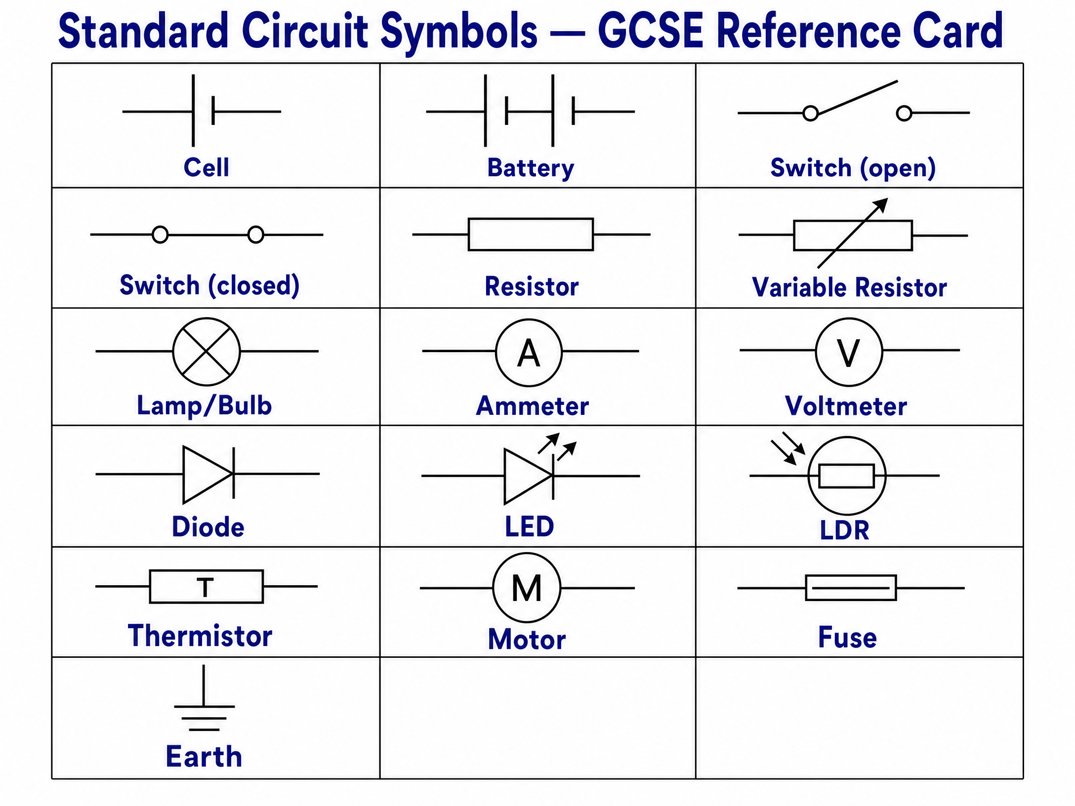
Circuit diagrams use standard, internationally recognised symbols to represent physical components. This ensures clarity and consistency.

- Cell and Battery: A single cell provides the electrical energy. A battery consists of two or more cells connected together.
- Switches: An open switch breaks the circuit, preventing current flow. A closed switch completes the circuit.
- Resistors: A standard resistor has a fixed resistance. A variable resistor allows you to alter the resistance, which is useful for dimming lights or changing volume.
- Lamps: Also known as bulbs, these convert electrical energy into light and heat.
- Diodes and LEDs: A diode only allows current to flow in one direction. An LED (Light Emitting Diode) is a diode that emits light when current flows through it.
- LDRs and Thermistors: An LDR (Light Dependent Resistor) decreases in resistance as light intensity increases. A thermistor decreases in resistance as temperature increases. Both are crucial for sensing circuits.
Concept 2: Series vs Parallel Circuits
The way components are connected fundamentally changes how the circuit behaves.

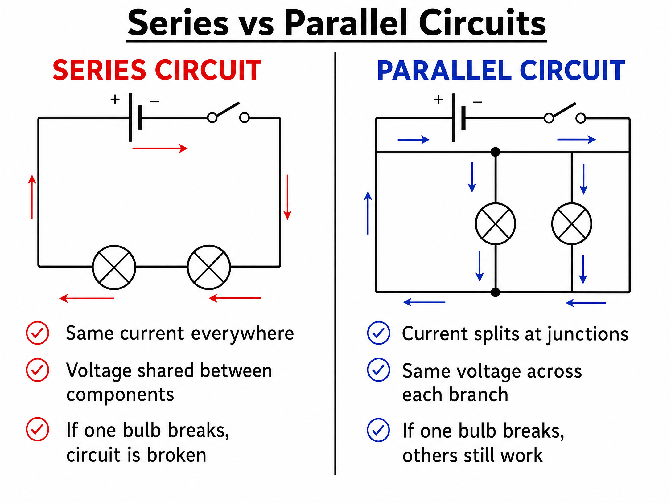
Series Circuits:
- Components are connected end-to-end in a single loop.
- There is only one path for the current, so the current is the same at all points.
- The total potential difference (voltage) of the supply is shared between the components.
- Crucial flaw: If one component breaks (e.g., a bulb blows), the circuit is broken and all components stop working.
Parallel Circuits:
- Components are connected on separate branches.
- The current splits at junctions, so the total current is the sum of the currents through each branch.
- The potential difference across each branch is the same as the supply potential difference.
- Major advantage: If one component breaks, the components on other branches continue to work independently. This is why domestic lighting is wired in parallel.
Concept 3: Measuring Instruments
Knowing how to measure current and voltage correctly is a frequent exam question.

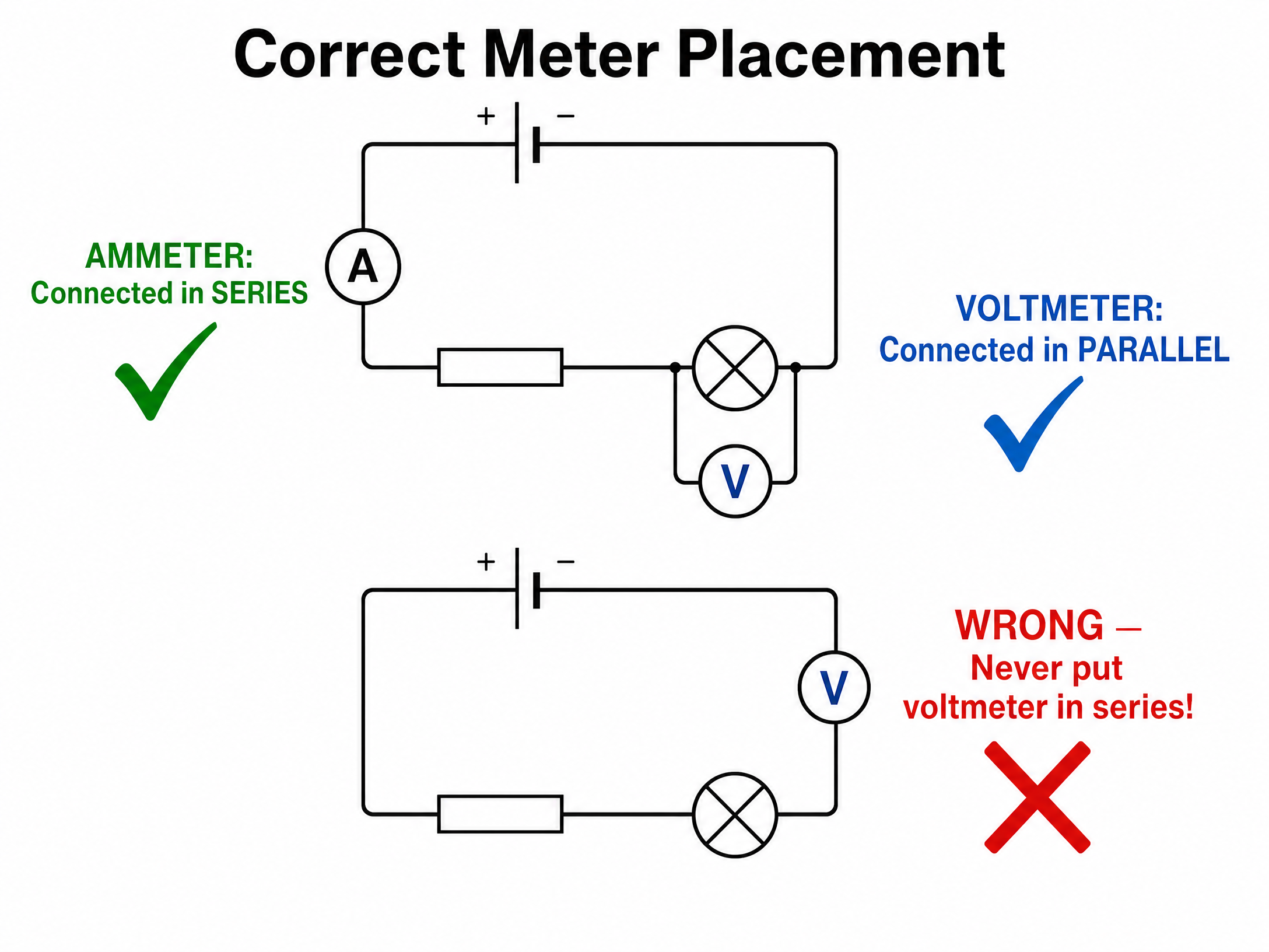
- Ammeter: Measures current (the rate of flow of charge). It must always be connected in series with the component you are investigating. Ammeters have very low resistance so they do not affect the current they are measuring.
- Voltmeter: Measures potential difference (voltage). It must always be connected in parallel across the component you are investigating. Voltmeters have very high resistance, so almost no current flows through them.
Mathematical/Scientific Relationships
While this specific subtopic focuses heavily on qualitative understanding and diagrams, it underpins the key electrical equations you will use later:
- Charge flow = current × time (Q = I t)
- Potential difference = current × resistance (V = I R)
Practical Applications
- Domestic Wiring: Your house is wired in parallel. If a bulb blows in the kitchen, the TV in the living room stays on.
- Sensing Circuits: LDRs are used in automatic street lights that turn on when it gets dark. Thermistors are used in central heating thermostats and fire alarms.
- Diodes: Used to protect delicate electronic equipment by ensuring current cannot flow backwards if a battery is inserted incorrectly.
Audio Revision
Listen to our 10-minute podcast episode for a deep dive into this topic, including an examiner's perspective on common mistakes and a quick-fire recall quiz.
Visual Resources
3 diagrams and illustrations
Interactive Diagrams
2 interactive diagrams to visualise key concepts
Conceptual Flow Outline
Flowchart showing how voltage behaves in different circuit types.
Conceptual Flow Outline
Flowchart showing how current behaves in different circuit types.
Worked Examples
3 worked examples — open one to explore the question and available guidance.
Practice Questions
Test your understanding — click to reveal model answers
Draw a circuit diagram containing a cell, a switch, and a lamp connected in series. Add an ammeter to measure the current through the lamp, and a voltmeter to measure the potential difference across the lamp.
Hint: Remember the 'A is Along, V is aVoid' rule for your meters.
A student builds a series circuit with a battery and two identical lamps. They then add a third identical lamp in series. Explain what happens to the brightness of the lamps.
Hint: Think about how voltage is distributed in a series circuit.
Explain how an LDR can be used to automatically turn on a street light when it gets dark.
Hint: Relate light intensity to resistance, and then to current.
A circuit contains a battery and two resistors connected in parallel. Explain what happens to the total current supplied by the battery if a third resistor is added in parallel.
Hint: Think about how adding branches affects the overall resistance of the circuit.
Identify the circuit symbol that consists of a rectangle with a diagonal line drawn through it, and describe its function.
Hint: It is related to temperature.