Pearson Edexcel · GCSE · Combined Science
Electromagnetic induction
Master the principles of electromagnetic induction, transformers, and the national grid. This topic is essential for understanding how electricity reaches our homes and is a frequent source of high-mark calculation and explanation questions in the exam.
- 4 min read
- 3 worked examples
- 5 practice questions
- 6 key terms
Study Notes
Overview

Welcome to Topic 13: Electromagnetic Induction. This topic bridges the gap between magnetism and electricity, explaining how the movement of a magnet can generate an electrical current. It is the fundamental principle behind almost all global electricity generation.
In Combined Science, this topic is critical because it brings together your knowledge of circuits, energy transfer, and magnetism. Examiners frequently test this area using a mix of calculation questions (using the transformer equation) and extended writing questions (explaining how transformers or the national grid work).
🎧 Listen to the Topic Podcast
Key Concepts
Concept 1: Electromagnetic Induction
Electromagnetic induction occurs when a conductor (like a wire) experiences a changing magnetic field. This changing field induces (creates) a potential difference (voltage) across the ends of the conductor. If the conductor is part of a complete circuit, a current will flow.
You can induce a potential difference in two main ways:
- Moving a magnet into or out of a coil of wire.
- Moving a wire through a magnetic field.
Crucial Examiner Point: The magnetic field must be changing. If you hold a magnet stationary inside a coil, no potential difference is induced.
Concept 2: Transformers

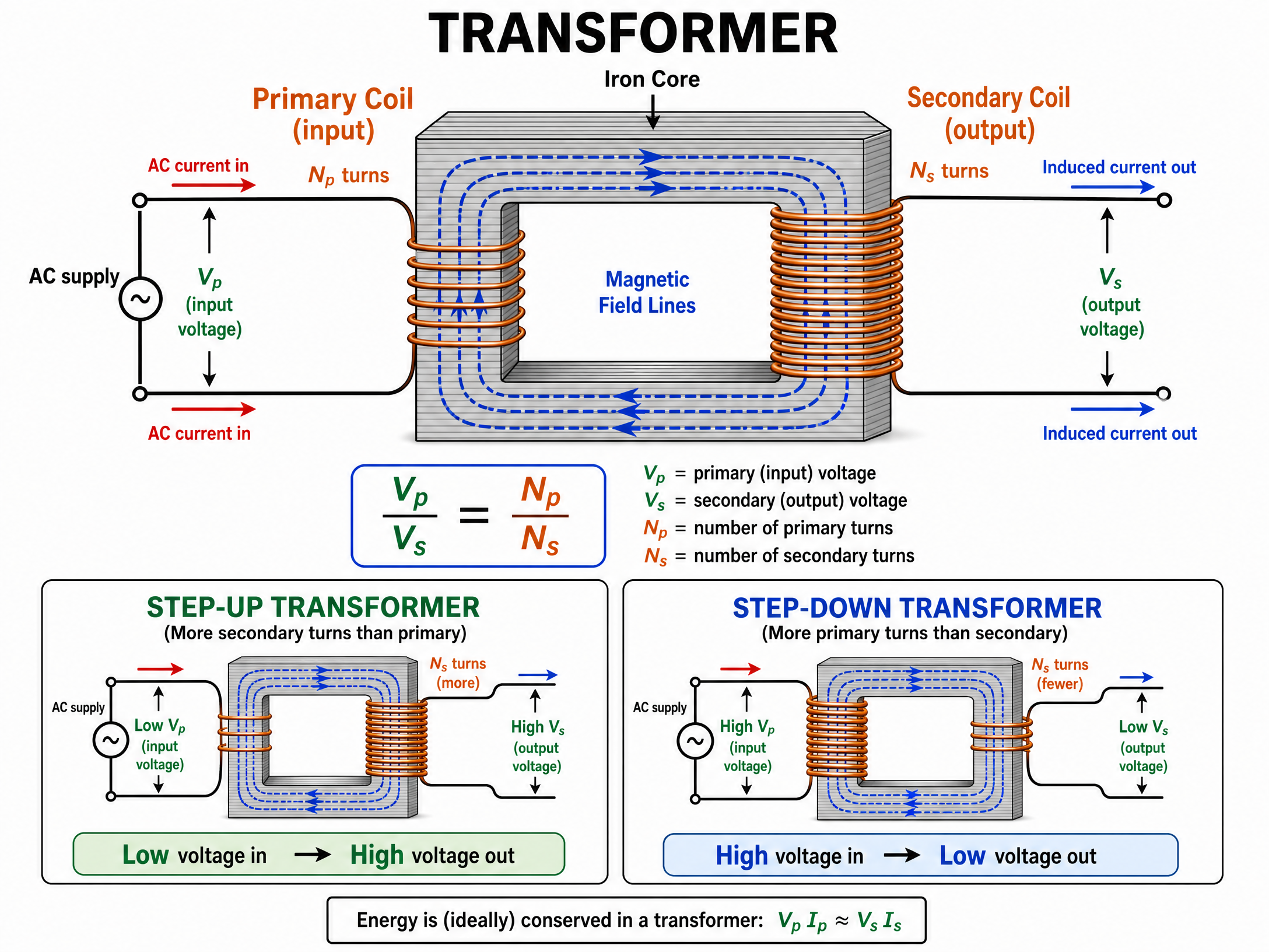
A transformer is a device that changes the potential difference of an alternating current (a.c.). It consists of a primary coil and a secondary coil wound around a laminated iron core.
How it works (Learn this sequence for 4-6 mark questions):
- An alternating current flows through the primary coil.
- This creates a constantly changing magnetic field around the primary coil and within the iron core.
- The iron core channels this changing magnetic field through the secondary coil.
- Because the secondary coil experiences a changing magnetic field, an alternating potential difference is induced across it.
Why a.c. only? Transformers will not work with direct current (d.c.) because d.c. produces a constant magnetic field. Without a changing magnetic field, no potential difference is induced in the secondary coil.
Concept 3: The National Grid

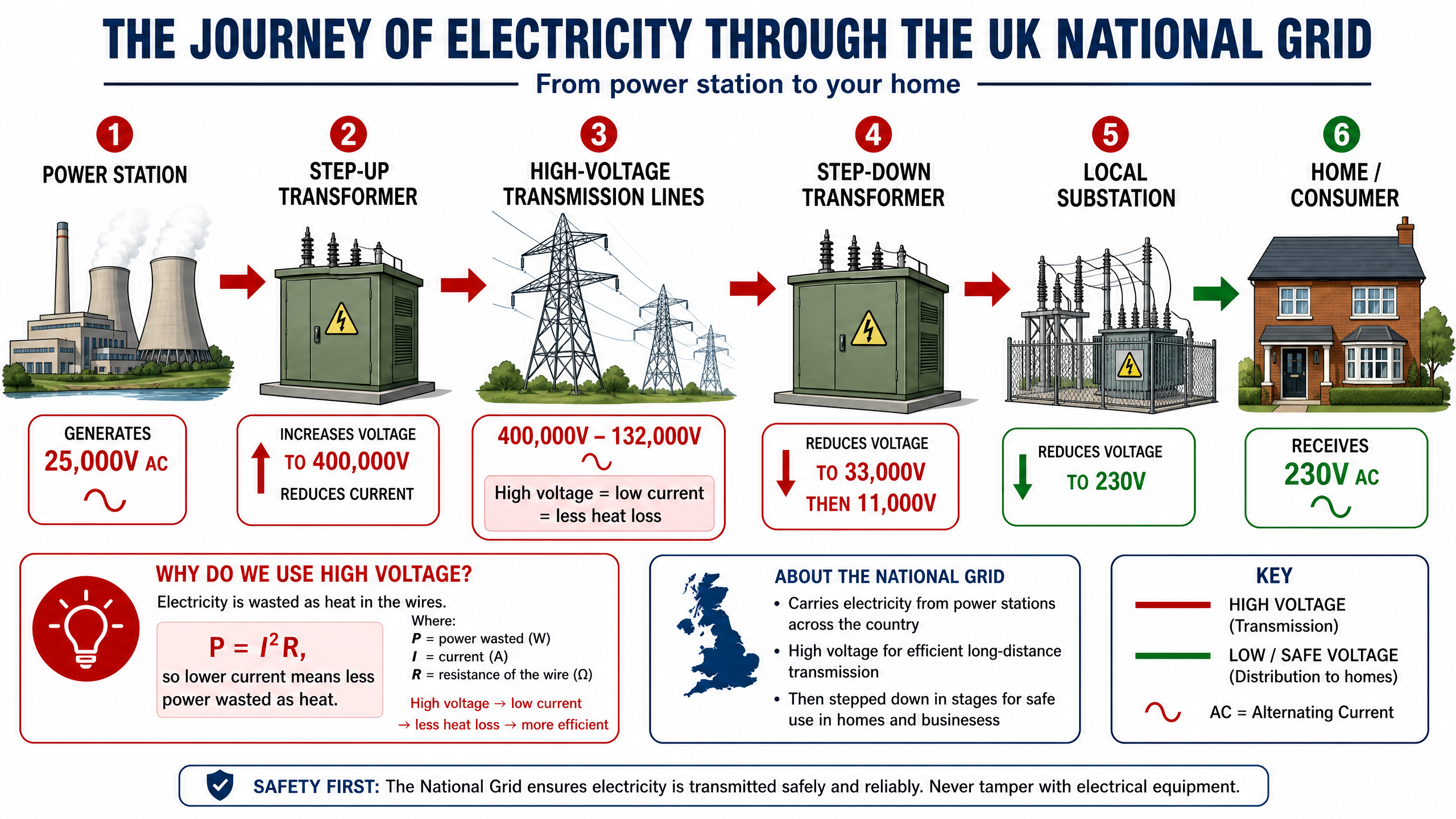
The National Grid is a system of cables and transformers linking power stations to consumers. Its primary goal is to transmit electricity as efficiently as possible by minimising energy lost as heat to the surroundings.
The Journey:
- Power Station: Generates electricity (e.g., at 25,000 V).
- Step-up Transformer: Increases the potential difference (e.g., to 400,000 V). Because P = IV, increasing V means the current (I) is significantly reduced.
- Transmission Cables: The electricity travels through the cables at low current. Since power lost as heat is calculated by P = I^2R, a low current drastically reduces thermal energy loss, making the system highly efficient.
- Step-down Transformer: Decreases the potential difference to safer, usable levels (e.g., 230 V) before it enters homes.
Mathematical/Scientific Relationships
1. The Transformer Equation (Given on formula sheet)
\frac{V_p}{V_s} = \frac{N_p}{N_s}
- V_p = potential difference across primary coil (V)
- V_s = potential difference across secondary coil (V)
- N_p = number of turns on primary coil
- N_s = number of turns on secondary coil
2. Power Equation for Ideal Transformers (Higher Tier - Must memorise)
Assuming 100% efficiency (power input = power output):
V_p \times I_p = V_s \times I_s
- V_p, V_s = potential difference (V)
- I_p, I_s = current (A)
3. Power Loss in Cables (Must memorise)
P = I^2 R
- P = power lost as heat (W)
- I = current (A)
- R = resistance of the cables (\Omega)
Practical Applications
- Phone Chargers: The plug of your phone charger contains a small step-down transformer to reduce the 230V mains supply to the 5V required by your phone battery.
- Microphones and Speakers: Dynamic microphones use electromagnetic induction. Sound waves cause a coil to vibrate past a magnet, inducing a current that represents the sound.
Visual Resources
2 diagrams and illustrations
Interactive Diagrams
2 interactive diagrams to visualise key concepts
Conceptual Flow Outline
Step-by-step logical sequence of how a transformer works. Memorise this sequence for 4-mark explanation questions.
Conceptual Flow Outline
The National Grid energy transfer pathway.
Worked Examples
3 worked examples — open one to explore the question and available guidance.
Practice Questions
Test your understanding — click to reveal model answers
State what is meant by electromagnetic induction. (2 marks)
Hint: Think about what is created, and what must happen to the magnetic field.
A student connects a transformer to a 12V d.c. battery. Explain why there is no output potential difference across the secondary coil. (2 marks)
Hint: What kind of magnetic field does d.c. produce?
A step-up transformer has 50 turns on its primary coil and 2000 turns on its secondary coil. The input potential difference is 12 V. Calculate the output potential difference. (3 marks)
Hint: Use the formula Vp/Vs = Np/Ns
Explain how a step-down transformer works. You should refer to the primary coil, the core, and the secondary coil in your answer. (4 marks)
Hint: Follow the logical sequence from input to output.
(Higher Tier) Power stations generate electricity at 25 kV. This is stepped up to 400 kV for transmission. Explain the advantage of transmitting electricity at 400 kV rather than 25 kV. (4 marks)
Hint: Link voltage, current, and thermal energy loss.