Pearson Edexcel · GCSE · Design and Technology
How electronic systems provide functionality to products and processes, including sensors, control devices and outputs
This topic covers how electronic systems provide functionality to products and processes, focusing on the essential roles of sensors, control devices, and outputs. Understanding these systems is crucial for designing smart, responsive products in modern Design and Technology.
- 6 min read
- 3 worked examples
- 3 practice questions
- 6 key terms
Study Notes
Overview
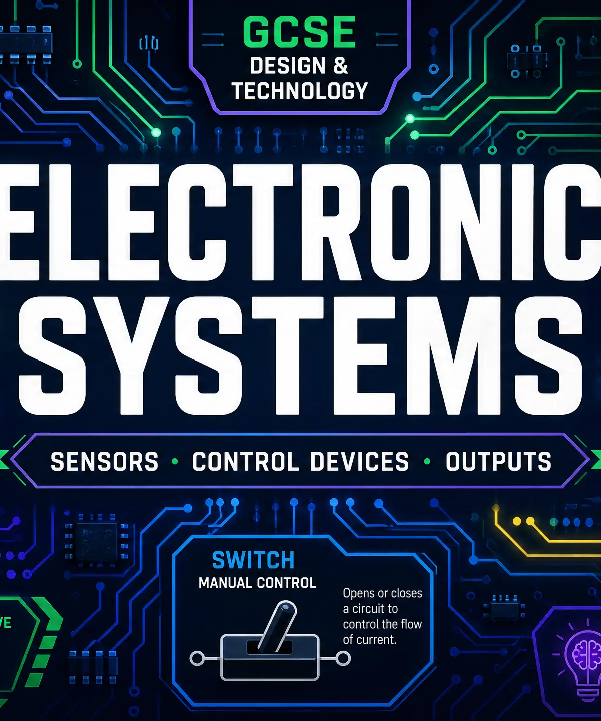
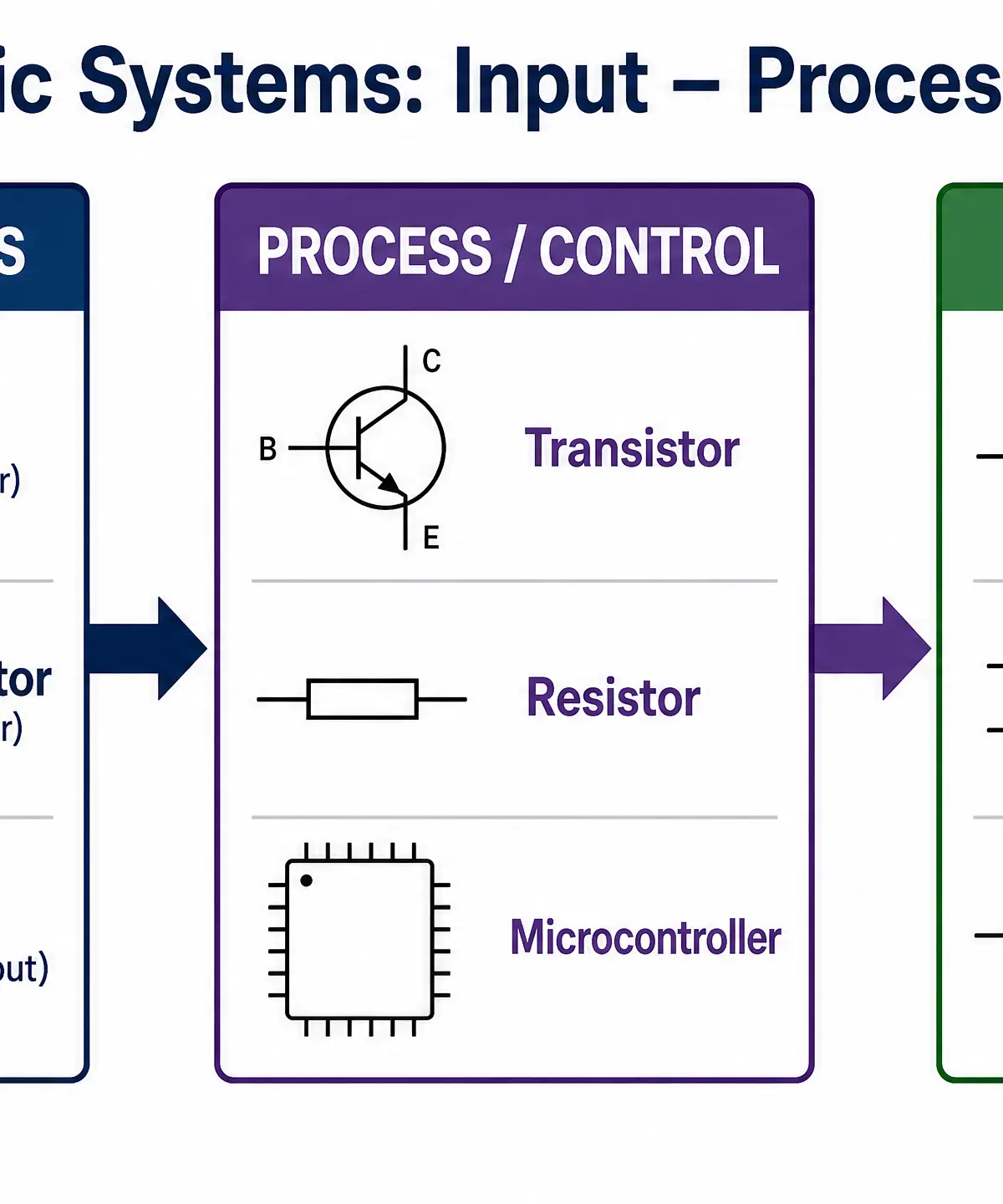
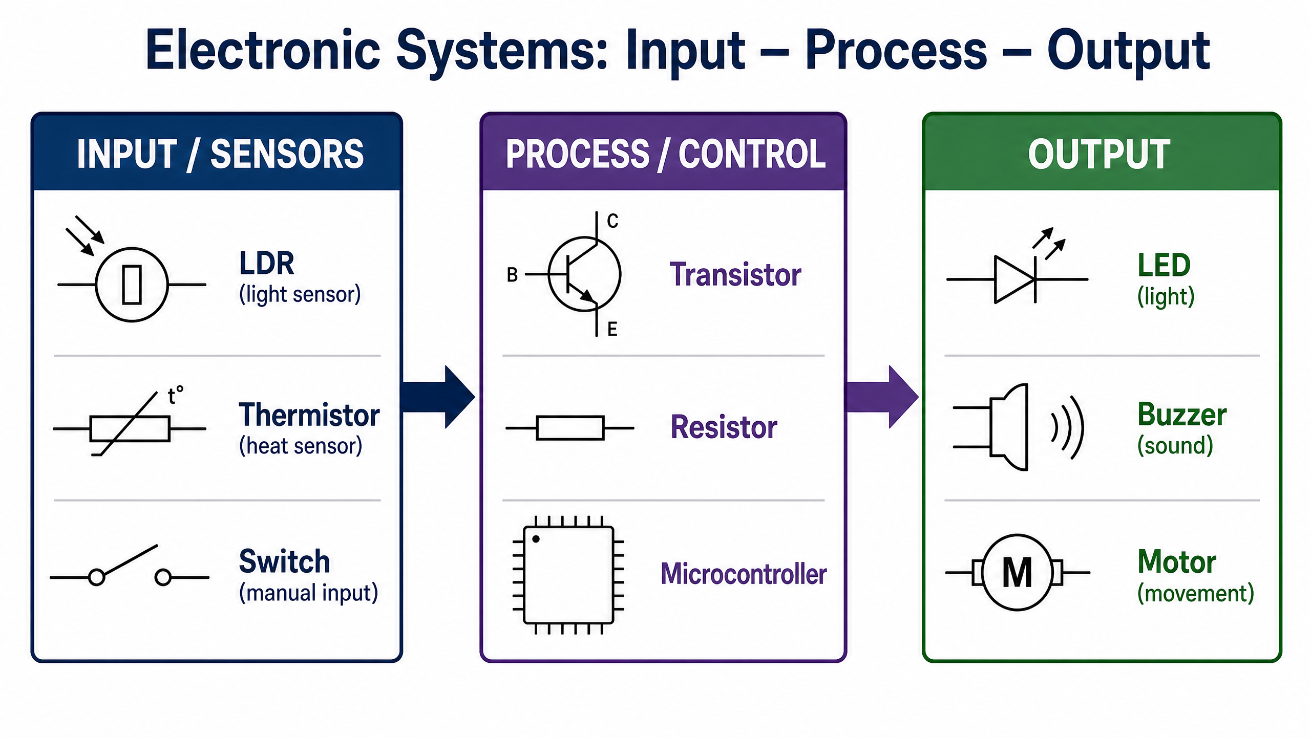
Electronic systems are the 'brains' behind modern products, allowing them to sense their environment, make decisions, and produce a response. In GCSE Design and Technology, you must understand how these systems provide functionality to products and processes. Whether it's an automatic night light, a temperature-controlled fan, or a security alarm, all electronic systems follow a fundamental structure: Input → Process → Output.
Listen to our revision podcast to reinforce these concepts:

Key Knowledge & Theory
Core Concepts: The Systems Approach
To successfully answer exam questions and design working circuits for your coursework, you must master the three stages of an electronic system:
- Input Stage (Sensors): This is where the system detects changes in the physical environment (like light, heat, or movement) or receives manual instructions (like a button press). The sensor converts this physical change into an electrical signal.
- Process Stage (Control Devices): This is the 'decision-making' part of the circuit. It takes the electrical signal from the input, modifies it (e.g., amplifies it or compares it to a threshold), and decides whether to activate the output.
- Output Stage: This is where the electrical signal is converted back into a physical action (like light, sound, or movement) that the user can perceive.
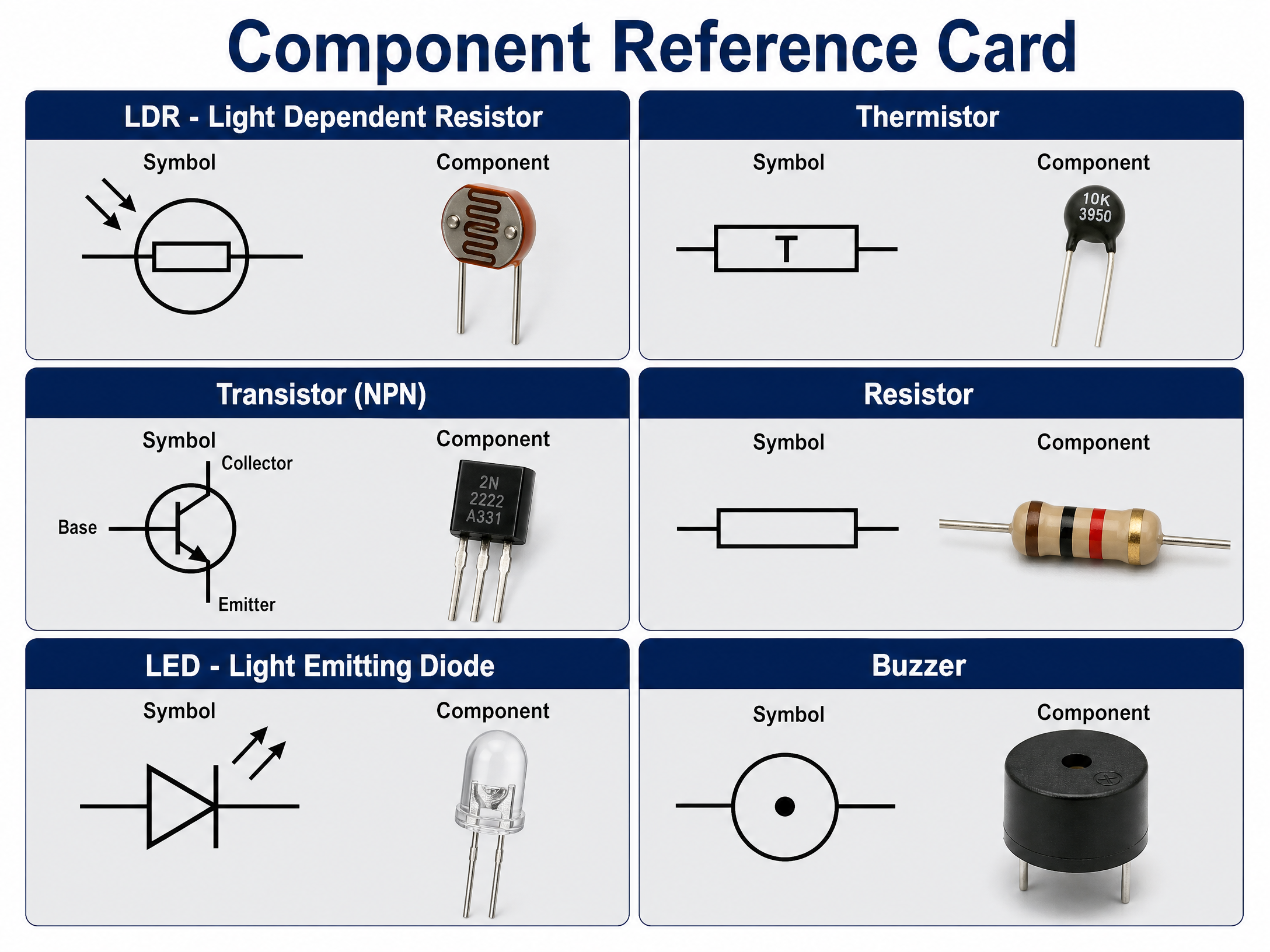
Component Reference
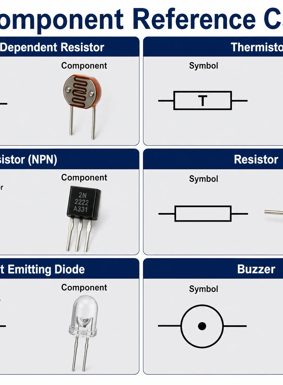
Technical Vocabulary
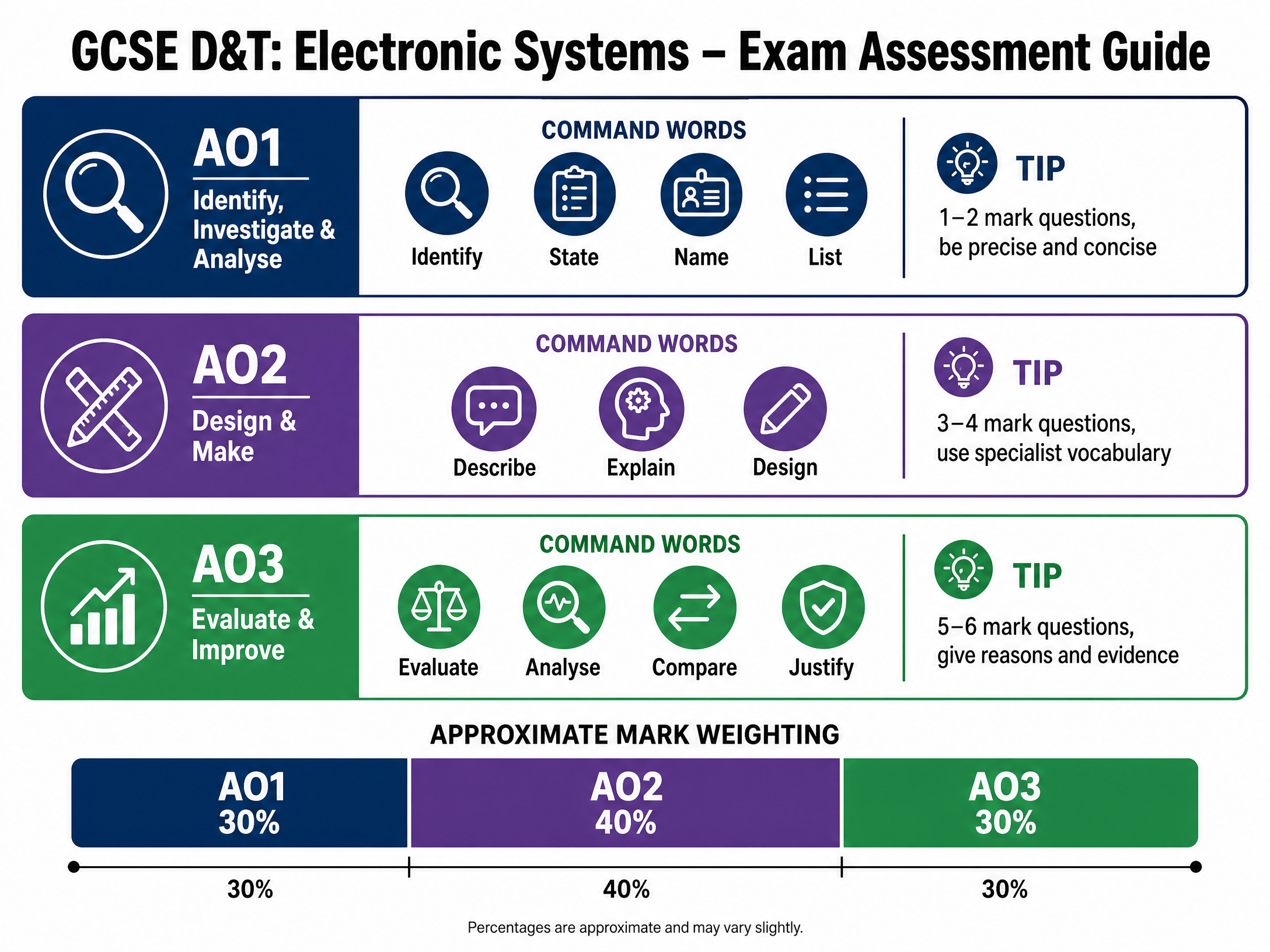
To access the highest mark bands (AO1 and AO2), you must use precise specialist terminology in both your written exam and portfolio annotation:
- Light-Dependent Resistor (LDR): An input component whose resistance decreases as light intensity increases.
- Thermistor (NTC): An input component whose resistance decreases as temperature increases.
- Transistor: A semiconductor device used to switch or amplify electrical signals. It has three terminals: Base, Collector, and Emitter.
- Resistor: A component that opposes the flow of electrical current, used to protect other components or divide voltage.
- Light-Emitting Diode (LED): An output component that emits light when current flows through it in the forward direction.
- Buzzer: An output component that converts electrical energy into sound energy.
Practical Skills
Circuit Design & Breadboarding
When designing electronic systems for your NEA (Non-Exam Assessment) portfolio, you must demonstrate practical competence. Before soldering components onto a Printed Circuit Board (PCB), you should prototype your circuit using a breadboard.
- Prototyping: Use a breadboard to test your circuit without soldering. This allows you to easily swap components (e.g., changing resistor values) to achieve the desired sensitivity for your sensors.
- Testing and Refining: If your LDR circuit turns the LED on when it's too bright rather than too dark, you must adjust the potential divider arrangement. Document these iterations in your portfolio.
- Soldering: When moving to a final PCB, ensure you use the correct heat settings and avoid 'dry joints' which can cause intermittent faults.
Materials & Equipment
- Multimeter: Essential for measuring resistance of sensors, checking voltage drops across components, and testing continuity.
- Wire Strippers & Snips: For preparing connecting wires neatly.
- Soldering Iron & Solder: Used for creating permanent electrical connections on PCBs or stripboards.
Portfolio/Coursework Guidance
Assessment Criteria
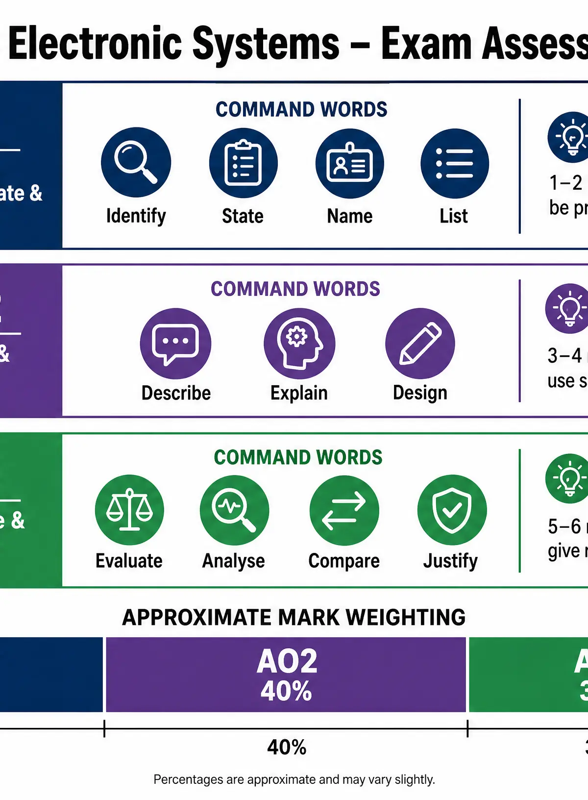
Examiners look for a clear link between your theoretical knowledge and practical application. If your product includes an electronic system, you must justify why you chose specific components.
- Poor Annotation: "I used an LDR to make the light turn on."
- Strong Annotation: "I incorporated an LDR in a potential divider circuit. As ambient light levels drop, the LDR's resistance increases, raising the voltage at the transistor's base, which acts as an electronic switch to activate the LED array."
Building a Strong Portfolio
- Show Iteration: Include photographs of your breadboard prototypes. Explain what didn't work initially and how you fixed it (e.g., "The LED was too dim, so I recalculated the series resistor value using Ohm's Law").
- Circuit Diagrams: Always include clear, correctly drawn circuit diagrams using standard standard symbols alongside your physical models.
Exam Component
Written Exam Knowledge
The written paper will test your ability to identify components from their symbols, explain their function, and analyse how a given circuit works. You will frequently encounter scenarios where you must explain the sequence of events in a system.
Top Tip for Systems Questions: Always trace the path of logic from the Input → through the Process → to the Output. Use the phrase "which causes..." to link your points.
Designing Under Exam Conditions
You may be asked to draw a block diagram or a simple circuit diagram to solve a specific problem (e.g., "Design a system to alert a gardener when a greenhouse gets too hot").
- Identify the Input: Heat = Thermistor.
- Identify the Process: Needs a switch = Transistor.
- Identify the Output: Alert = Buzzer or LED.
- Draw and Label: Draw the blocks/symbols clearly and label the flow of signals.
Visual Resources
3 diagrams and illustrations
Interactive Diagrams
1 interactive diagram to visualise key concepts
Conceptual Flow Outline
The logical flow of an automated electronic system
Worked Examples
3 worked examples — open one to explore the question and available guidance.
Practice Questions
Test your understanding — click to reveal model answers
Identify the component represented by a rectangle with a line drawn diagonally through it, ending in a small flat line.
Hint: Think about components that sense temperature.
Describe the function of a resistor in a circuit containing an LED.
Hint: What happens if too much current flows through a delicate component?
A student is designing a temperature warning system for a computer server room. The system must sound an alarm if the room gets too hot. Explain how a thermistor, transistor, and buzzer can be used to achieve this.
Hint: Use the Input-Process-Output structure. Remember TURD (Temperature Up, Resistance Down).