Pearson Edexcel · GCSE · Design and Technology
Systems: Design contexts
This topic covers the fundamental principles of Systems in Design and Technology, focusing on how electronic components interact to solve problems. It bridges the gap between theoretical knowledge of inputs, processes, and outputs, and the practical application of manufacturing techniques and material selection for enclosures.
- 8 min read
- 3 worked examples
- 4 practice questions
- 6 key terms
Study Notes
Overview

Welcome to Systems: Design Contexts. This topic is central to understanding how modern electronic products function, from simple motion-activated security lights to complex smart home devices. In this unit, you will explore the relationship between electronic components, the manufacturing processes used to assemble them, and the materials chosen to protect them. You will also consider the environmental and social responsibilities that designers hold when creating electronic products.
Listen to the companion podcast for this topic:

Key Knowledge & Theory
Core Concepts
The Systems Approach
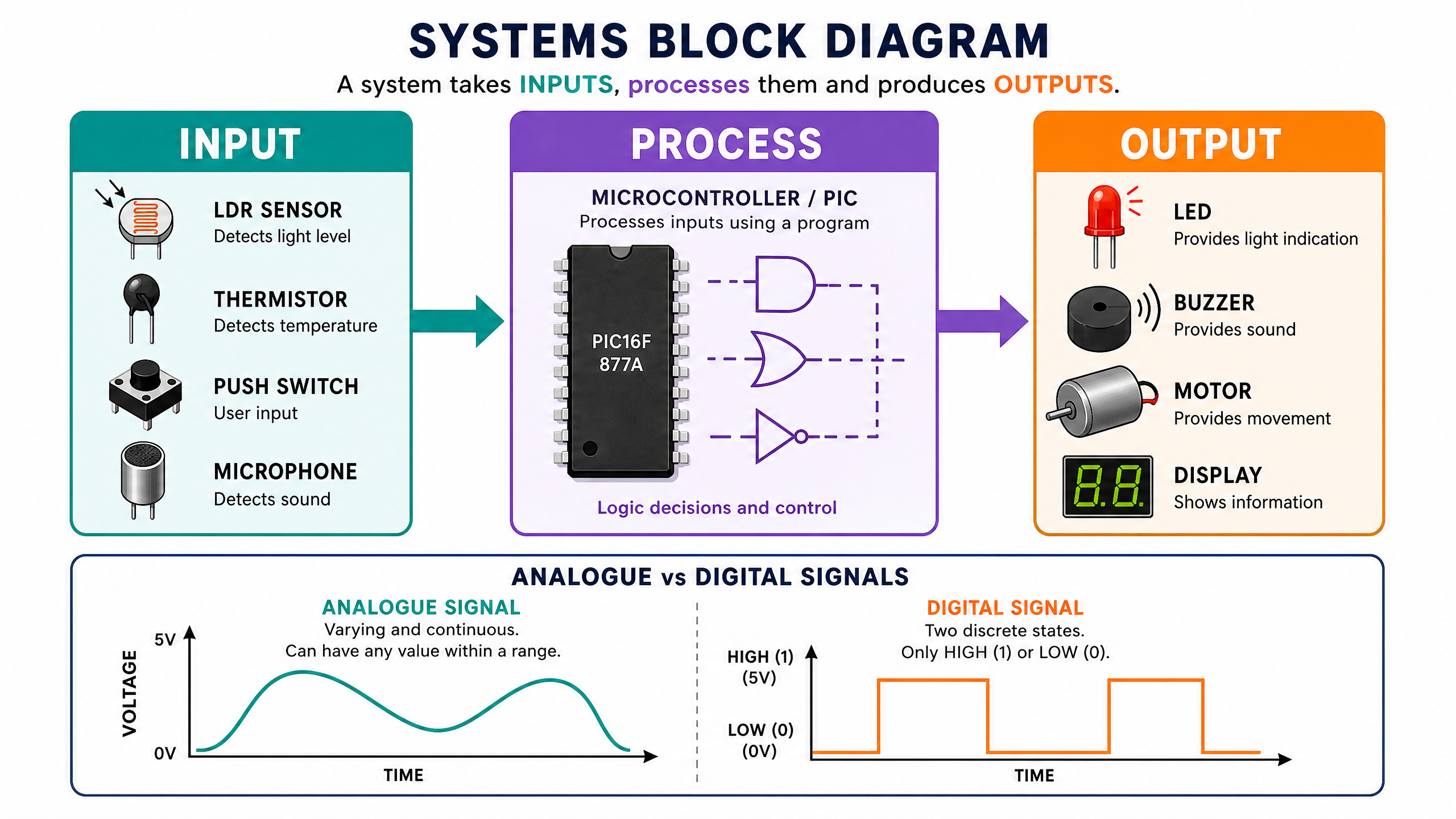
Every electronic product can be analysed using a systems approach, which breaks the product down into three distinct stages: Input, Process, and Output.
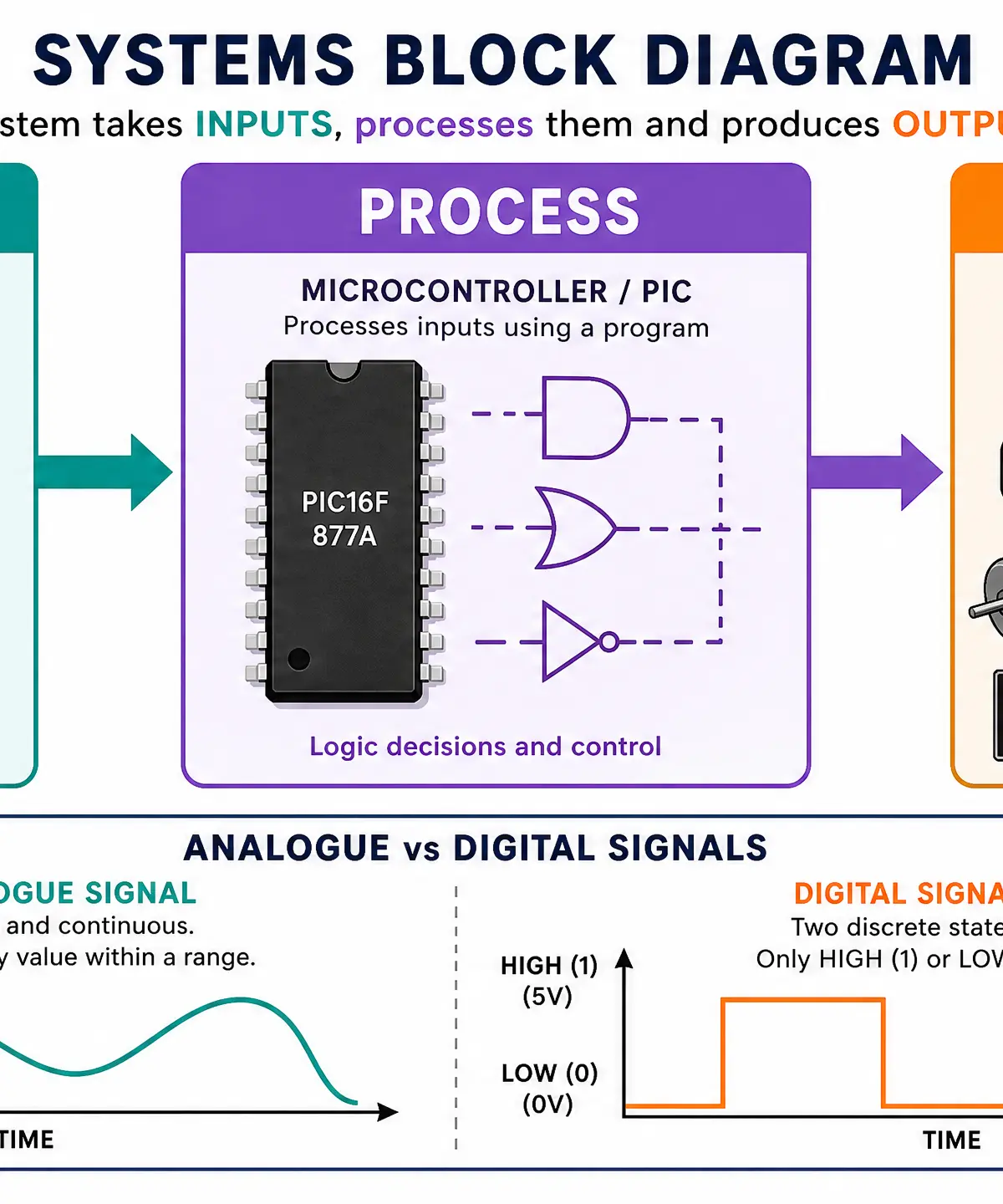
- Input: The system receives information from the environment. This is typically achieved using sensors or switches. Examples include Light Dependent Resistors (LDRs) for light, thermistors for temperature, and push-to-make switches for user interaction.
- Process: The system makes a decision based on the input signal. This is usually handled by a microcontroller (such as a PIC chip) programmed with specific logic (e.g., IF light level is low AND motion is detected, THEN activate output).
- Output: The system responds with an action. This could be visual (LEDs, displays), auditory (buzzers, speakers), or mechanical (motors, solenoids).
Analogue vs. Digital Signals
It is crucial to understand the difference between analogue and digital signals.
- Analogue signals vary continuously and can take any value within a given range. For example, a thermistor produces an analogue signal because temperature changes smoothly.
- Digital signals have only two discrete states: HIGH (typically 5V, representing a logic '1') and LOW (0V, representing a logic '0'). Microcontrollers process digital signals. Therefore, analogue inputs often require an Analogue-to-Digital Converter (ADC) before the microcontroller can use the data.
Ohm's Law and Resistor Calculations
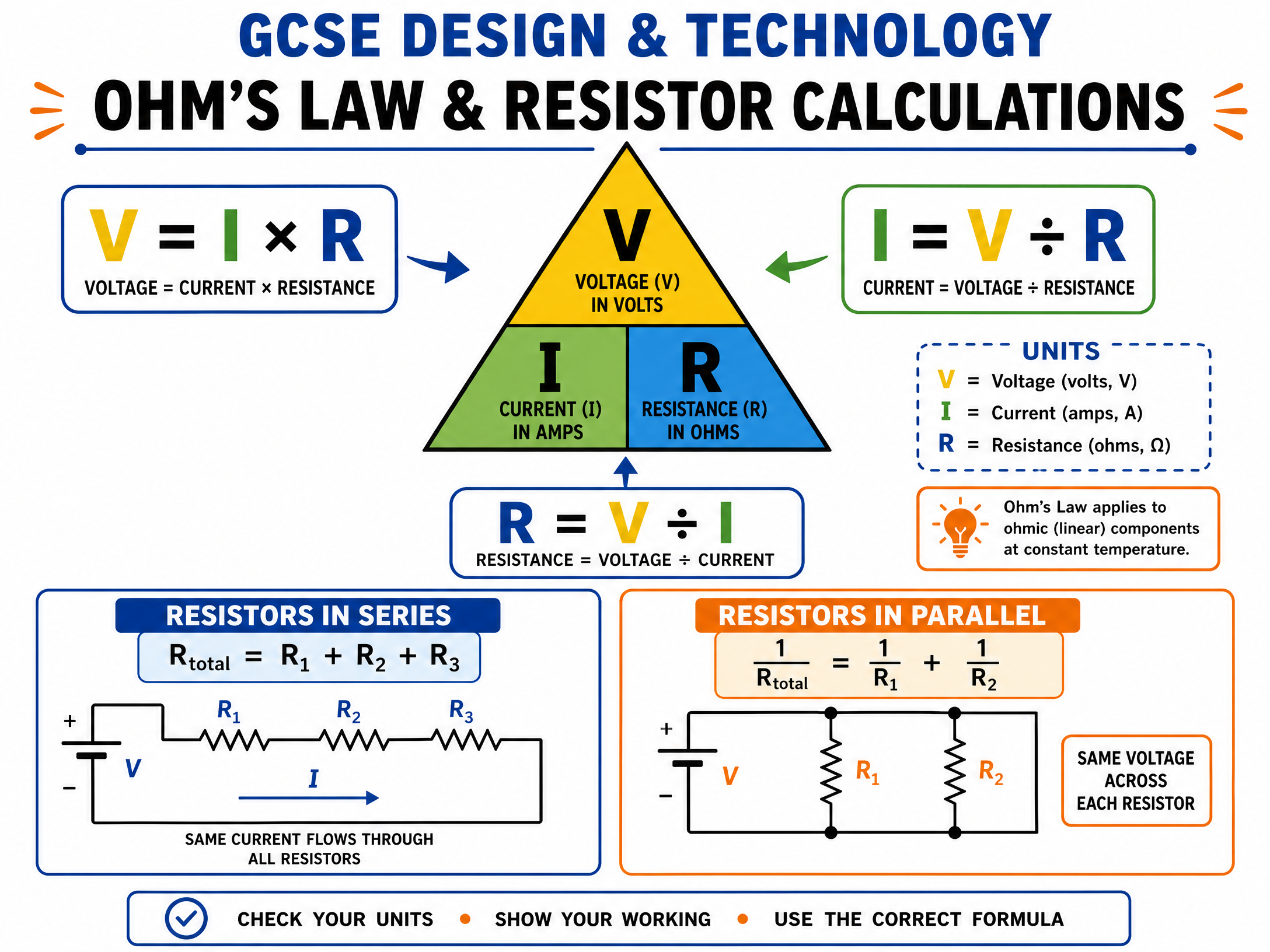
Ohm's Law is a fundamental principle governing electronic circuits. It defines the relationship between Voltage (V), Current (I), and Resistance (R).
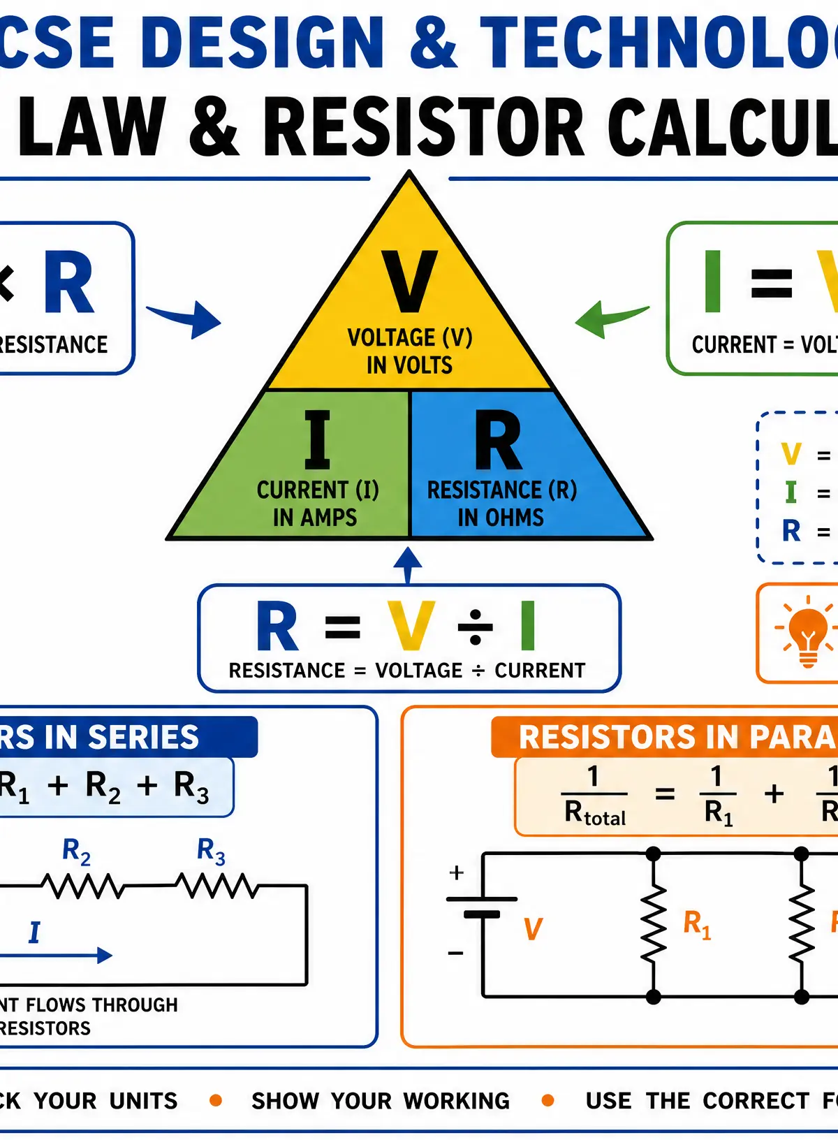
- Formula: V = I \times R
- Units: Voltage is measured in Volts (V), Current in Amps (A), and Resistance in Ohms (\Omega).
When calculating total resistance in a circuit, the method depends on how the resistors are arranged:
- Series: Resistors are connected end-to-end. The total resistance is the sum of all individual resistances: R_{total} = R_1 + R_2 + R_3
- Parallel: Resistors are connected across multiple branches. The formula is: \frac{1}{R_{total}} = \frac{1}{R_1} + \frac{1}{R_2}
Key Legislation and Directives
| Directive | Meaning | Key Requirements | Relevance to Design |
|---|---|---|---|
| RoHS | Restriction of Hazardous Substances | Restricts the use of specific hazardous materials (e.g., lead, mercury, cadmium) in electrical and electronic equipment. | Designers must specify compliant, lead-free solder and components to prevent toxic leaching in landfills. |
| WEEE | Waste Electrical and Electronic Equipment | Mandates that manufacturers take responsibility for the end-of-life disposal and recycling of their products. | Encourages designing for disassembly, using recyclable materials, and reducing built-in obsolescence. |
Technical Vocabulary
- Microcontroller: A compact integrated circuit designed to govern a specific operation in an embedded system.
- Through-Hole Technology (THT): A mounting scheme where component leads are inserted into holes drilled in a printed circuit board (PCB) and soldered to pads on the opposite side.
- Surface Mount Technology (SMT): A method where components are mounted directly onto the surface of a PCB.
- Built-in Obsolescence: A policy of planning or designing a product with an artificially limited useful life, so it will become obsolete (unfashionable or no longer functional) after a certain period of time.
Practical Skills
Techniques & Processes
PCB Assembly Methods
Understanding how components are attached to a PCB is essential for both theory questions and practical coursework.
- Through-Hole Technology (THT):
- Process: Leads are pushed through drilled holes and soldered manually or via wave soldering.
- Advantages: Strong mechanical bonds; ideal for components undergoing mechanical stress (like connectors); easier for manual prototyping and repair.
- Disadvantages: Requires drilling (adding cost/time); takes up more board space; generally slower for mass production.
- Surface Mount Technology (SMT):
- Process: Solder paste is applied to pads, components are placed on top (often by pick-and-place machines), and the board passes through a reflow oven to melt the solder.
- Advantages: Components are much smaller; components can be placed on both sides of the board; highly automated and fast for mass production.
- Disadvantages: Weaker mechanical bonds; difficult to prototype or repair by hand.
Materials & Equipment
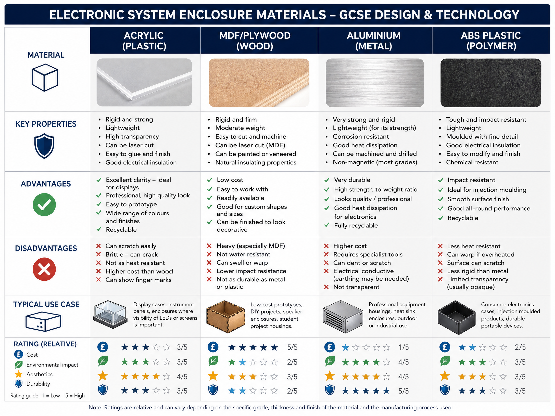
Enclosure Materials
Choosing the right material for an enclosure requires balancing aesthetics, protection, cost, and environmental impact.
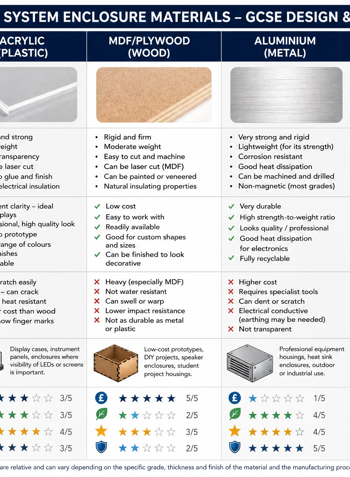
- Acrylic (Polymer): Excellent optical clarity, easily laser cut, good electrical insulator. Use: Display cases, student prototypes.
- MDF/Plywood (Manufactured Board): Low cost, easy to machine. Use: Low-cost prototyping, speaker cabinets. Drawback: Poor moisture resistance.
- Aluminium (Metal): High strength-to-weight ratio, excellent heat dissipation, fully recyclable. Use: High-end audio equipment, heat sinks.
- ABS (Polymer): High impact resistance, excellent for injection moulding. Use: Consumer electronics (remote controls, power tool casings).
Portfolio/Coursework Guidance
Assessment Criteria
Examiners are looking for evidence that you can apply theoretical knowledge to practical design problems. Marks are awarded for:
- AO1 (Investigate): Identifying appropriate components and materials for a specific user need.
- AO2 (Design): Generating and developing ideas, including schematic diagrams and PCB layouts.
- AO3 (Make): Demonstrating safe and accurate manufacturing skills (e.g., soldering, laser cutting enclosures).
- AO4 (Evaluate): Testing the final system and evaluating its performance and environmental impact against the specification.
Building a Strong Portfolio
- Annotate Everything: Do not just present a circuit diagram. Annotate it to explain why you chose a specific resistor value or why you opted for an LDR over a photodiode.
- Show Iteration: Document your prototyping phase. If a circuit didn't work on the breadboard, explain how you used a multimeter to fault-find and correct the issue.
- Justify Material Choices: Explicitly link your choice of enclosure material to the product's environment. (e.g., "I selected ABS for the outdoor sensor housing due to its high impact resistance and ability to withstand environmental degradation compared to MDF.")
Exam Component
Written Exam Knowledge
The written paper will heavily test your ability to calculate values (Ohm's Law) and justify design decisions. You must be prepared to compare manufacturing methods (SMT vs THT) and evaluate the environmental footprint of electronic products.
Practical Exam Preparation
If your course includes a timed practical assessment, ensure you are confident in reading schematic diagrams, translating them to breadboards or stripboards, and using a soldering iron safely and efficiently.
Visual Resources
3 diagrams and illustrations
Interactive Diagrams
1 interactive diagram to visualise key concepts
Conceptual Flow Outline
The Electronic Systems Design Process
Worked Examples
3 worked examples — open one to explore the question and available guidance.
Practice Questions
Test your understanding — click to reveal model answers
Identify one input device that could be used to detect changes in temperature. (1 mark)
Hint: Think about components whose resistance changes with heat.
A circuit contains two resistors in series: R_1 = 200\Omega and R_2 = 300\Omega. The circuit is powered by a 5V supply. Calculate the total current flowing through the circuit. (3 marks)
Hint: First find the total resistance for a series circuit, then use Ohm's Law.
Explain why Aluminium is often chosen over MDF for the enclosure of a high-power audio amplifier. (4 marks)
Hint: Think about the specific properties of metal versus wood, especially regarding heat and durability.
Evaluate the environmental impact of modern consumer electronics, with reference to manufacturing, use, and disposal. (8 marks)
Hint: Structure your answer to cover all three stages mentioned in the question. Use terms like RoHS, WEEE, and built-in obsolescence.