Pearson Edexcel · GCSE · Design and Technology
Systems: Stock forms, types and sizes in order to calculate and determine the quantity of components required
This topic covers the essential knowledge needed to identify, select, and calculate the correct electronic components for a design. Understanding stock forms, package types, and how to apply Ohm's Law and resistance formulas is crucial for both your coursework portfolio and the written exam.
- 6 min read
- 3 worked examples
- 4 practice questions
- 6 key terms
Study Notes

Overview
Topic 5.5 focuses on the physical reality of electronic systems. When designing a circuit, you don't just pick a component based on its theoretical function; you must specify its physical size, its tolerance, and how it will be assembled onto a Printed Circuit Board (PCB). This topic bridges the gap between circuit diagrams and manufactured products.
Listen to the revision podcast below for a comprehensive overview of this topic:

Key Knowledge & Theory
Stock Forms and Supply
Electronic components are supplied in various stock forms depending on how they will be used in manufacturing:
- Loose Components: Supplied in bags or boxes. Best for educational use, prototyping, or low-volume hand assembly.
- Tape and Reel: Components are held in a continuous paper or plastic tape wound onto a reel. This is essential for automated pick-and-place machines in mass production.
- Cut Tape: A short length of tape cut from a reel. Useful for small production runs where a full reel isn't needed.
- Tubes/Trays: Used for larger components like microcontrollers or Integrated Circuits (ICs) to protect their delicate pins.
Component Package Types
There are two primary ways components are mounted to a PCB:
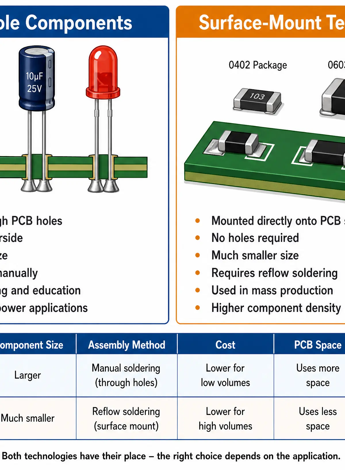
- Through-Hole Technology (THT): Components have wire leads that pass through holes drilled in the PCB and are soldered on the underside. They are physically larger, mechanically strong, and easy to handle, making them ideal for school projects and prototyping.
- Surface-Mount Technology (SMT): Components are soldered directly onto pads on the surface of the PCB. They have no leads. They are extremely small (e.g., 0402 or 0603 packages) and allow for high-density, double-sided PCBs. SMT is the standard for commercial mass production.
Resistor Values and the E12 Series
It is impossible to manufacture a resistor to an exact value every time. Therefore, resistors are manufactured to standard preferred values known as the E-series. For GCSE, you must know the E12 Series.
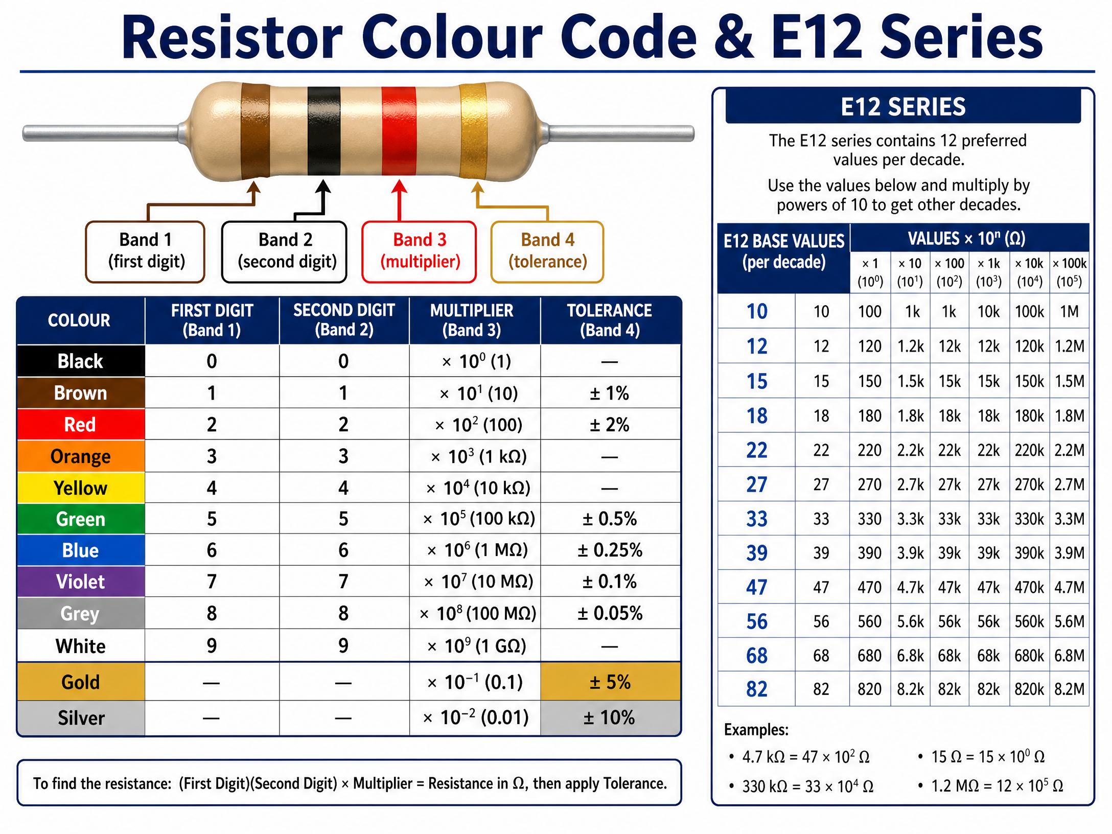
The E12 series provides 12 base values per decade: 10, 12, 15, 18, 22, 27, 33, 39, 47, 56, 68, 82.
These base values are then multiplied by powers of 10. For example, from the base value '47', you can get a 47\Omega, 470\Omega, 4.7k\Omega, or 47k\Omega resistor.
Resistor Colour Codes
Through-hole resistors use coloured bands to indicate their value and tolerance.
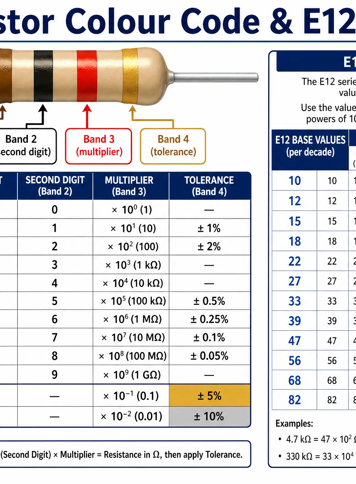
For a standard 4-band resistor:
- Band 1: First digit
- Band 2: Second digit
- Band 3: Multiplier (number of zeros to add)
- Band 4: Tolerance (Gold = \pm5%, Silver = \pm10%)
Practical Skills: Calculations
Calculations are a major source of marks in the exam. You must show your working out to gain method marks.
Ohm's Law
Ohm's Law states that Voltage (V) equals Current (I) multiplied by Resistance (R).
V = I \times R
- V is Voltage in Volts (V)
- I is Current in Amps (A)
- R is Resistance in Ohms (\Omega)
CRITICAL TIP: Always convert your units before calculating. If current is given in milliamps (mA), divide by 1000 to convert to Amps. If resistance is given in kilohms (k\Omega), multiply by 1000 to convert to Ohms.
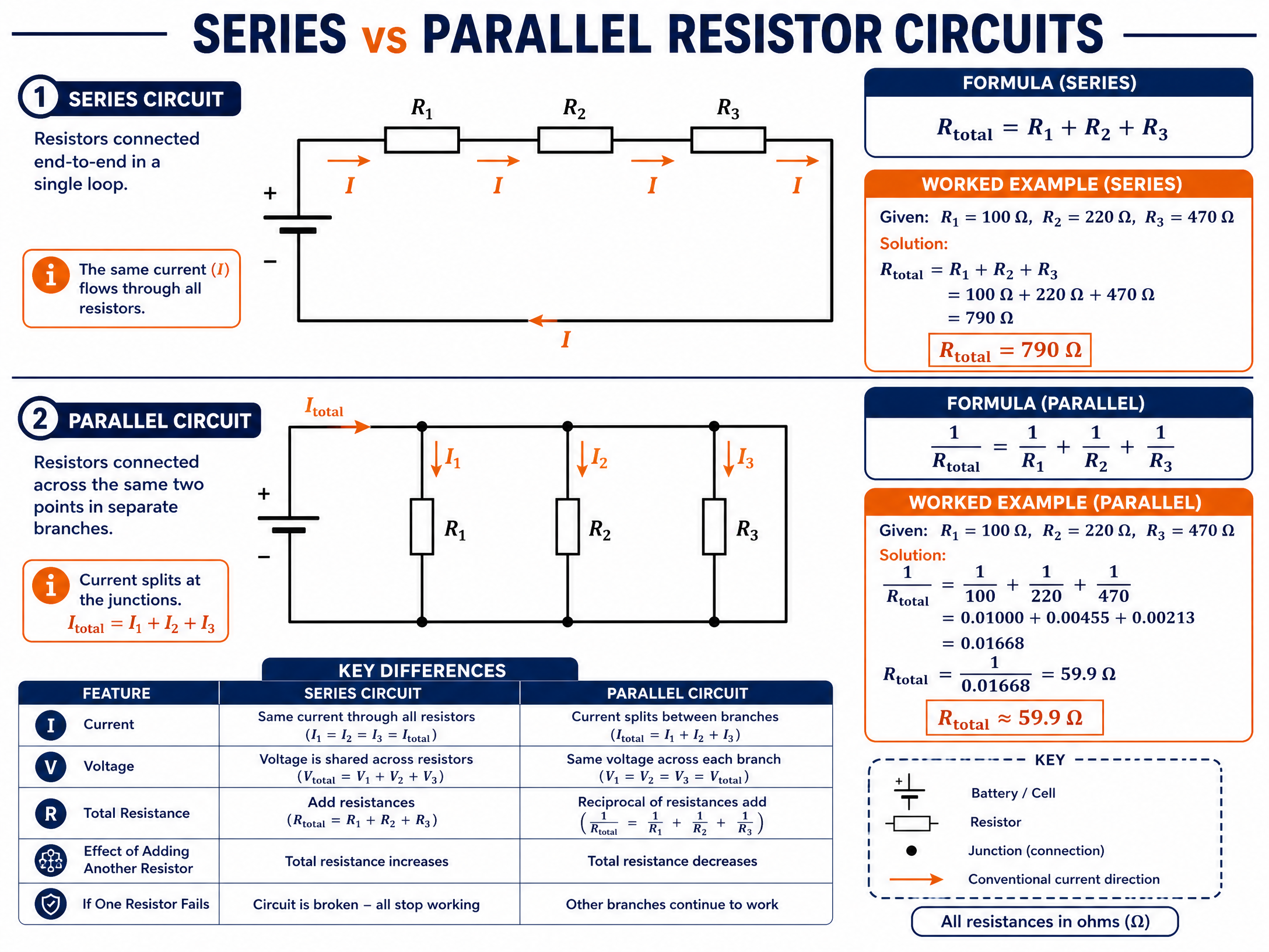
Series and Parallel Resistors
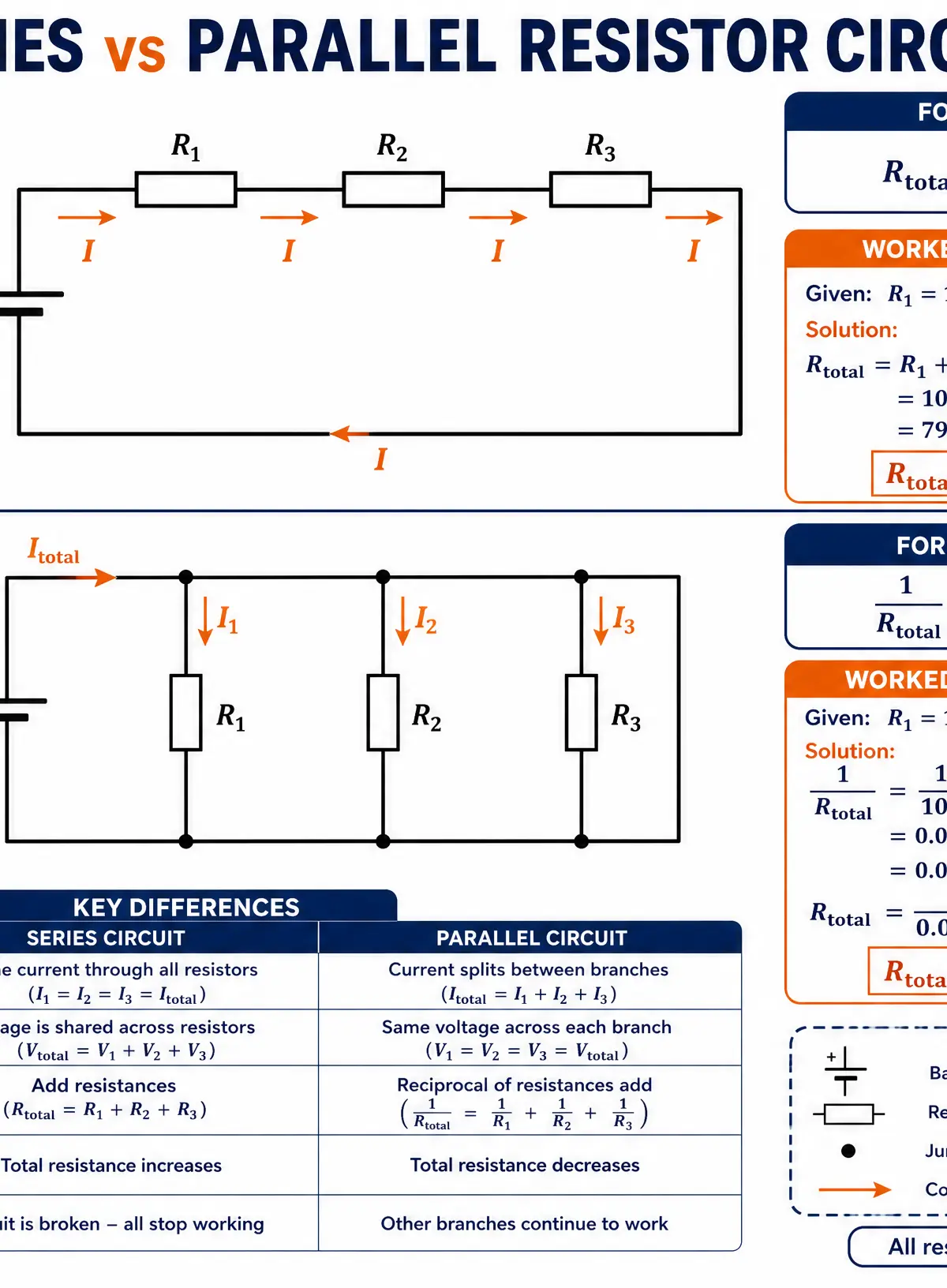
Resistors in Series:
When connected end-to-end, the total resistance is the sum of the individual resistances.
R_{total} = R_1 + R_2 + R_3
Resistors in Parallel:
When connected across the same two points, the total resistance is calculated using the reciprocal formula.
\frac{1}{R_{total}} = \frac{1}{R_1} + \frac{1}{R_2} + \frac{1}{R_3}
Self-Check: The total resistance of a parallel circuit will always be less than the value of the smallest individual resistor.
Portfolio/Coursework Guidance
Assessment Criteria
Examiners look for evidence that you have considered the physical realities of your electronic design, not just the theory.
- Design Development: Show that you have calculated the correct resistor values for your LEDs or timing circuits using Ohm's Law.
- Manufacturing Specification: When listing components, specify the package type (e.g., "Through-hole" or "SMT") and the tolerance required.
- Justification: Explain why you chose a specific component form. For a school prototype, state that through-hole components were selected for ease of manual soldering.
Building a Strong Portfolio
Include a clear Bill of Materials (BOM) in your coursework. A strong BOM includes:
- Component Name (e.g., Resistor)
- Value and Unit (e.g., 330\Omega)
- Tolerance (e.g., \pm5%)
- Package Type (e.g., Through-hole, 0.25W)
- Quantity Required
Exam Component
Written Exam Knowledge
The written exam will test your ability to perform calculations, interpret colour codes, and justify manufacturing choices.
- Calculation Questions (AO2): You will be given a circuit scenario and asked to calculate missing values. Always show the formula, the substitution of values, and the final answer with correct units.
- Context Questions (AO3): You may be asked to compare manufacturing methods for a batch of 10,000 radios versus a single prototype. You must discuss SMT vs Through-hole, automated pick-and-place vs hand soldering, and tape-and-reel vs loose components.
Exam Strategy
- Time Management: Allocate roughly 1 minute per mark. A 3-mark calculation question should take about 3 minutes.
- Sanity Check: Does your answer make sense? If you calculate a current of 50 Amps for a small LED circuit, you have likely forgotten to convert kilohms to ohms.
Visual Resources
3 diagrams and illustrations

Interactive Diagrams
1 interactive diagram to visualise key concepts
Conceptual Flow Outline
Process for selecting resistor values based on calculations and the E12 series.
Worked Examples
3 worked examples — open one to explore the question and available guidance.
Practice Questions
Test your understanding — click to reveal model answers
Identify the value and tolerance of a resistor with the colour bands: Yellow, Violet, Red, Gold. (2 marks)
Hint: Use the BB ROY mnemonic. Yellow is 4, Violet is 7. The third band is the multiplier (number of zeros).
A circuit requires a 50\Omega resistor, but this is not a standard E12 value. Using only standard E12 series resistors, explain how you could achieve a total resistance of exactly 50\Omega. (3 marks)
Hint: Look at the E12 base values: 10, 12, 15, 18, 22, 27, 33, 39, 47, 56, 68, 82. How can you add two of these together to make 50?
A motor in a robotic toy draws a current of 250mA when connected to a 6V supply. Calculate the resistance of the motor. (3 marks)
Hint: Use Ohm's Law ($V = I \times R$). Remember to convert the current from milliamps to Amps before calculating.
Discuss the implications for a manufacturer switching from producing 100 prototype circuits using through-hole components to producing 100,000 final products using surface-mount technology (SMT). (6 marks)
Hint: Consider the impact on PCB size, assembly methods, machinery costs, component packaging (stock forms), and labour.