Pearson Edexcel · GCSE · Design and Technology
The functions of mechanical devices used to produce different sorts of movements, including changing of magnitude and direction of forces
This topic explores the fundamental mechanical devices used to control movement and force in engineered products. Understanding levers, cams, pulleys, and gears is essential for designing functional prototypes and forms a core component of the written exam.
- 8 min read
- 3 worked examples
- 4 practice questions
- 6 key terms
Study Notes
Overview
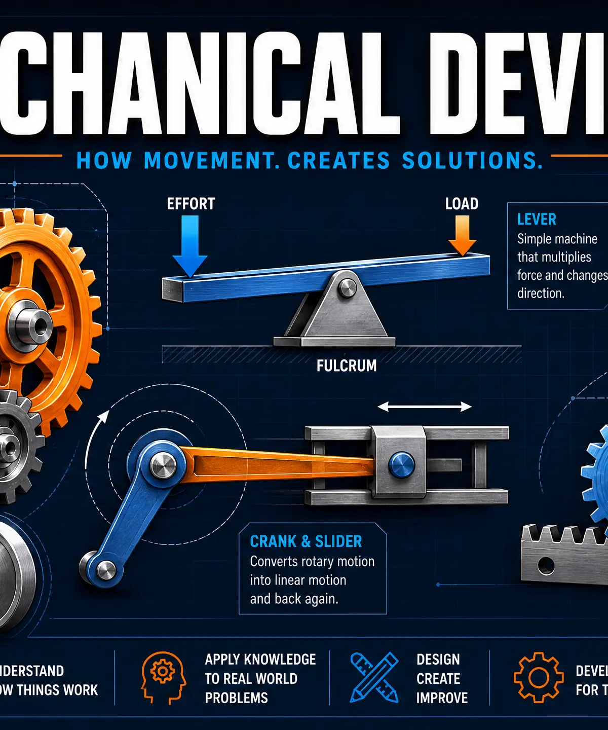
Mechanical devices are the building blocks of almost all moving products, from simple scissors to complex car engines. In GCSE Design and Technology, understanding how these devices produce movement and change the magnitude and direction of forces is crucial. This knowledge allows you to design functional, moving prototypes and is heavily tested in the written examination through both identification and calculation questions.
Key Knowledge & Theory
Types of Movement
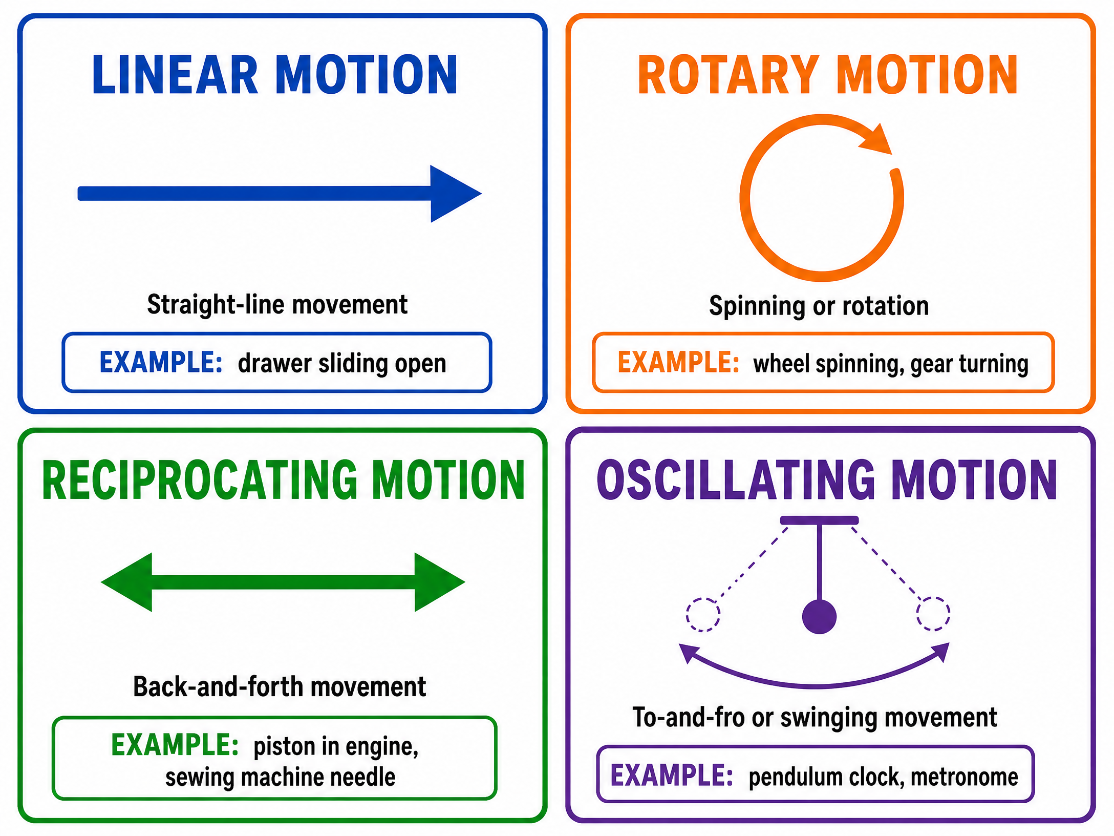
Before exploring specific devices, you must be able to identify the four fundamental types of movement. Examiners frequently ask candidates to state the type of motion produced by a specific mechanism.
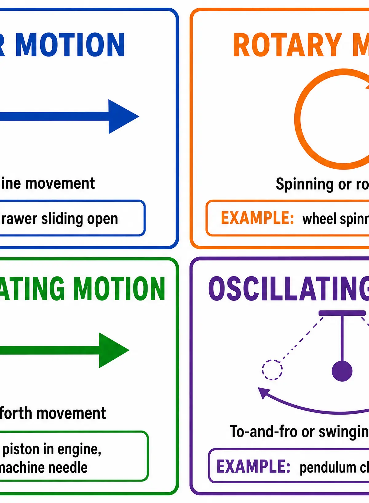
- Linear Motion: Movement in a straight line in one direction (e.g., a drawer sliding open or a paper trimmer cutting across a page).
- Rotary Motion: Circular movement around a central axis (e.g., a wheel turning, a drill bit spinning, or a gear rotating).
- Reciprocating Motion: Back-and-forth movement in a straight line (e.g., a sewing machine needle moving up and down, or a piston in a car engine).
- Oscillating Motion: A swinging, back-and-forth movement in an arc (e.g., a pendulum on a clock or a playground swing).
Levers
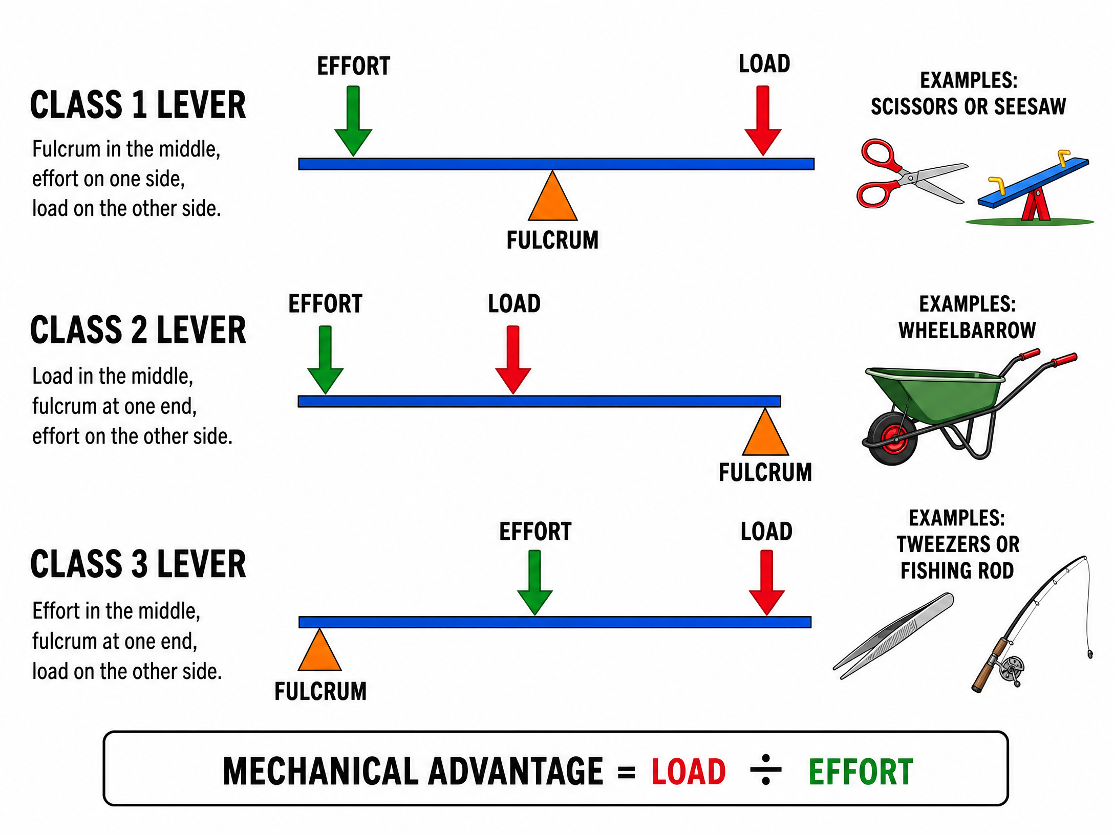
Levers are simple machines used to change the amount of effort required to move a load. They consist of a rigid bar that pivots on a fixed point called a fulcrum. The force you apply is the effort, and the object you are trying to move is the load.
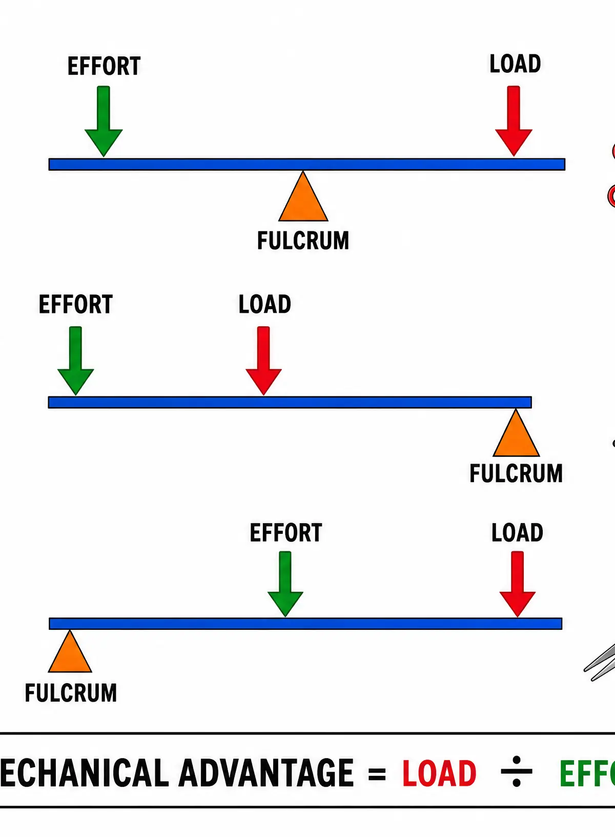
There are three classes of levers, determined by the relative positions of the fulcrum, effort, and load:
- Class 1 Lever: The fulcrum is positioned between the effort and the load.
- Examples: Scissors, seesaws, pliers.
- Function: Can provide a mechanical advantage or change the direction of force.
- Class 2 Lever: The load is positioned between the fulcrum and the effort.
- Examples: Wheelbarrows, nutcrackers.
- Function: Always provides a mechanical advantage (effort required is less than the load), but the effort must move a greater distance.
- Class 3 Lever: The effort is positioned between the fulcrum and the load.
- Examples: Tweezers, fishing rods, a human arm lifting a weight.
- Function: Does not provide a mechanical advantage (effort required is greater than the load), but the load moves a greater distance and at a faster speed.
Cams and Followers
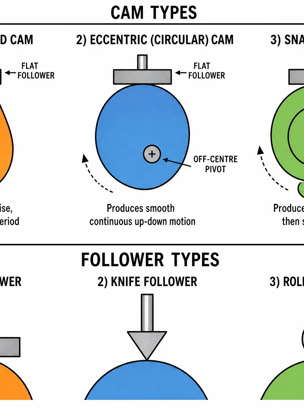
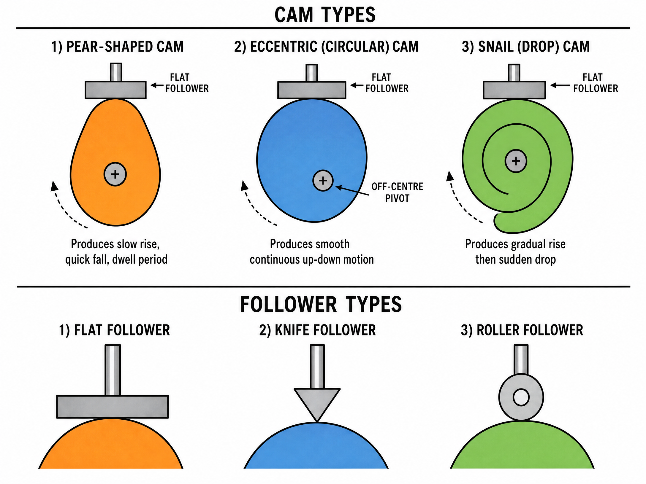
A cam mechanism is used to convert rotary motion into reciprocating (or sometimes oscillating) motion. It consists of two parts: the rotating cam and the follower, which rests on the edge of the cam and moves as the cam's profile changes.
Cam Profiles:
- Pear-shaped Cam: Produces a slow rise, a sudden drop, and then a period where the follower does not move (a 'dwell' period).
- Eccentric (Circular) Cam: A circular cam with the pivot point off-centre. It produces a smooth, continuous up-and-down reciprocating motion.
- Snail (Drop) Cam: Produces a slow, steady rise followed by a sudden, sharp drop. Often used in mechanisms that require a sudden release of energy.
Follower Types:
- Flat Follower: Has a flat base. Prone to high friction but simple to manufacture.
- Knife Follower: Has a sharp point. Highly accurate for following intricate cam profiles but wears down quickly.
- Roller Follower: Uses a small wheel. Reduces friction significantly, making it the most common choice in high-speed machinery.
Pulleys and Belts
Pulleys are wheels with a grooved edge designed to hold a rope, cable, or belt. They are used to transmit rotary motion or to lift heavy loads.
- Single Fixed Pulley: Changes the direction of the force (pulling down to lift a load up) but provides no mechanical advantage.
- Block and Tackle: A system of multiple pulleys that provides a mechanical advantage, making it easier to lift heavy loads.
- Belt and Pulley Systems: Used to transmit rotary motion from a driver pulley to a driven pulley. By using pulleys of different sizes, the speed of rotation can be changed.
Gear Trains
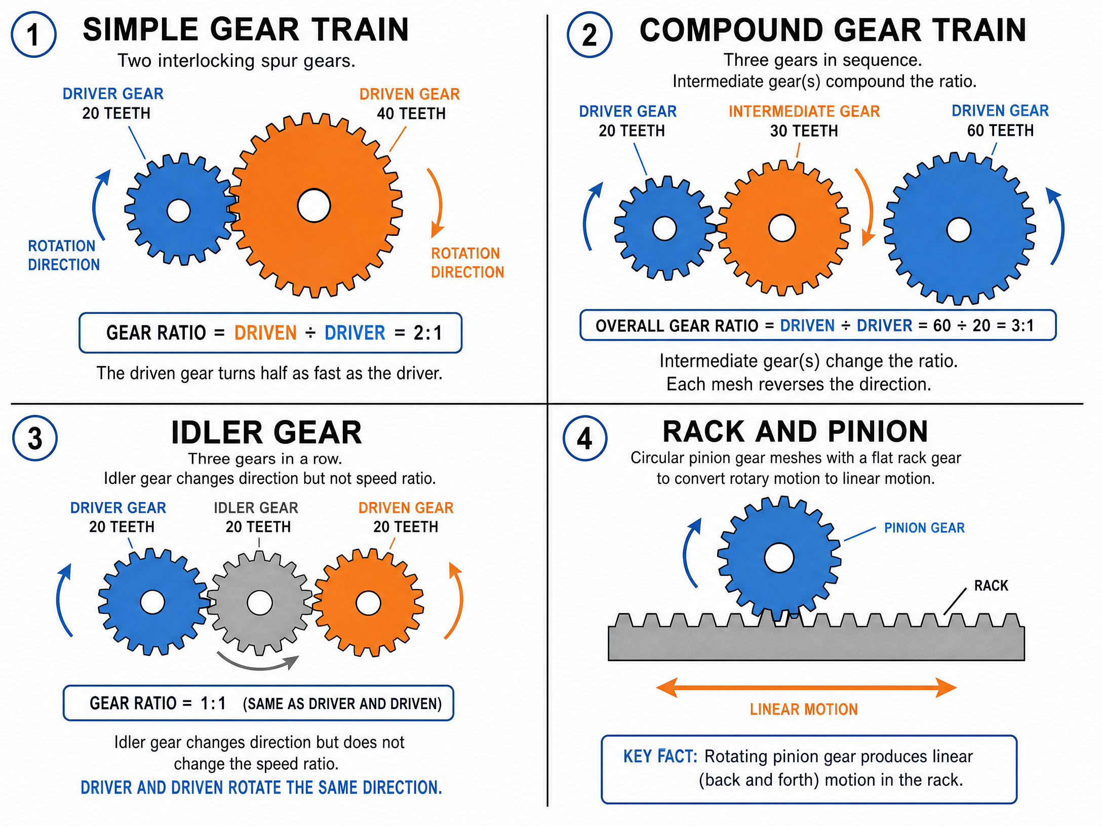
Gears are toothed wheels that mesh together to transmit rotary motion and torque. They are crucial for controlling the speed and power of mechanical systems.
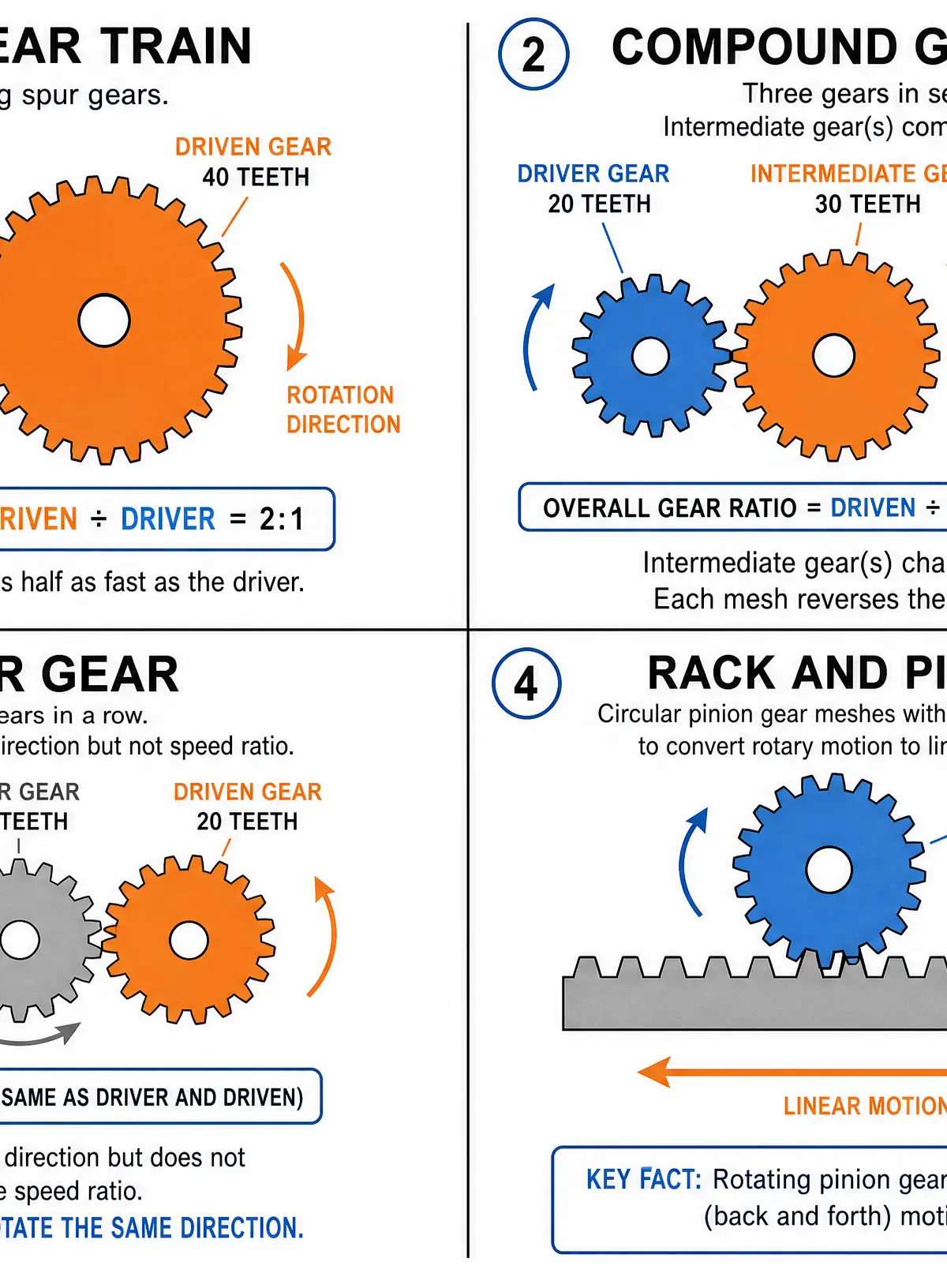
- Simple Gear Train: Consists of two meshing gears (a driver and a driven gear). They rotate in opposite directions.
- Idler Gear: A gear placed between the driver and driven gears. It ensures the driver and driven gears rotate in the same direction without affecting the overall gear ratio.
- Compound Gear Train: Involves multiple pairs of gears, with at least one shaft holding two gears. Used to achieve large gear ratios in a compact space.
- Bevel Gears: Used to transmit rotary motion through a 90-degree angle (e.g., in a hand drill).
- Rack and Pinion: A circular gear (pinion) meshes with a flat, toothed bar (rack). This converts rotary motion into linear motion (e.g., in car steering systems or tripod adjustments).
Practical Skills
Applying Mechanisms in Design
When designing your NEA (Non-Exam Assessment) prototype, examiners look for the purposeful application of mechanical devices to solve a problem.
- Identify the Required Motion: Determine what movement your product needs. Does a lid need to slide open (linear)? Does a character need to pop up (reciprocating)?
- Select the Appropriate Mechanism: If you need to convert the rotary motion of a motor into the reciprocating motion of a pump, a cam and follower or a crank and slider is appropriate.
- Calculate Ratios: If your motor spins too fast, use a belt and pulley system or a gear train to reduce the speed and increase the torque (turning force).
- Consider Friction and Wear: Ensure moving parts are appropriately lubricated or use low-friction materials (like nylon or PTFE) for bearings and followers.
Audio Revision
Listen to this 10-minute podcast episode covering the core concepts, common exam mistakes, and a quick-fire recall quiz.

Portfolio/Coursework Guidance
Assessment Criteria
For your NEA, marks are awarded for demonstrating technical understanding and practical application. If your product includes moving parts, you must explicitly document the mechanical principles behind them.
Evidencing Mechanical Understanding
- Working Drawings: Include clear, annotated diagrams of your mechanisms, identifying the driver, driven components, fulcrums, and types of motion.
- Calculations: Show the calculations for any gear ratios, velocity ratios, or mechanical advantage in your design. This proves you have engineered the solution, not just guessed.
- Modelling: Document your iterative modelling process. Show how you tested a cardboard or MDF linkage before making the final version in acrylic or aluminium. Explain why the first model failed and how you improved it.
Exam Component
Written Exam Knowledge
Topic 1.5 is heavily assessed in the written paper. You will face a mix of:
- Multiple Choice/Short Answer (AO1): Identifying mechanisms from diagrams or stating types of motion.
- Calculation Questions (AO2): Calculating gear ratios, output speeds, mechanical advantage, or velocity ratio. Always show your working.
- Extended Response (AO3): Explaining how a specific mechanism works within a given product context, evaluating its suitability, or comparing two different mechanisms.
Essential Formulas
You must memorize these formulas; they are rarely provided in the exam:
- Mechanical Advantage (MA) = Load ÷ Effort
- Velocity Ratio (VR) (Levers) = Distance moved by effort ÷ Distance moved by load
- Velocity Ratio (VR) (Pulleys) = Diameter of driven pulley ÷ Diameter of driver pulley
- Gear Ratio = Number of teeth on driven gear ÷ Number of teeth on driver gear
- Output Speed (RPM) = Input Speed (RPM) ÷ Gear Ratio (or VR)
- Efficiency (%) = (Mechanical Advantage ÷ Velocity Ratio) × 100
Visual Resources
4 diagrams and illustrations
Interactive Diagrams
1 interactive diagram to visualise key concepts
Conceptual Flow Outline
Process flow: Using gearing to increase torque
Worked Examples
3 worked examples — open one to explore the question and available guidance.
Practice Questions
Test your understanding — click to reveal model answers
State the type of motion produced by a pendulum swinging on a grandfather clock. (1 mark)
Hint: Think about the L-R-R-O acronym. Which one means swinging in an arc?
A lever is used to lift a 200N paving slab. The user applies a downward effort of 50N. Calculate the Mechanical Advantage. (2 marks)
Hint: Remember the formula: MA = Load ÷ Effort.
Explain why a roller follower is often preferred over a knife follower in high-speed engine mechanisms. (2 marks)
Hint: Think about what happens when two metal surfaces rub together rapidly.
A pillar drill uses a belt and pulley system. The motor is attached to a driver pulley with a diameter of 40mm, spinning at 1200 RPM. This drives a pulley on the drill spindle with a diameter of 120mm. Calculate the Velocity Ratio and the output speed of the drill spindle. (4 marks)
Hint: Calculate VR first (Driven ÷ Driver). Then use VR to find the output speed (Input Speed ÷ VR).