Pearson Edexcel · GCSE · Design and Technology
The use of programmable components to embed functionality into products
This topic covers how programmable components (microcontrollers) are embedded into products to create intelligent, responsive systems. You'll learn the Input-Process-Output model, how to draw flowcharts, and how to apply this knowledge in both theory exams and practical coursework.
- 5 min read
- 2 worked examples
- 3 practice questions
- 6 key terms
Study Notes
Overview
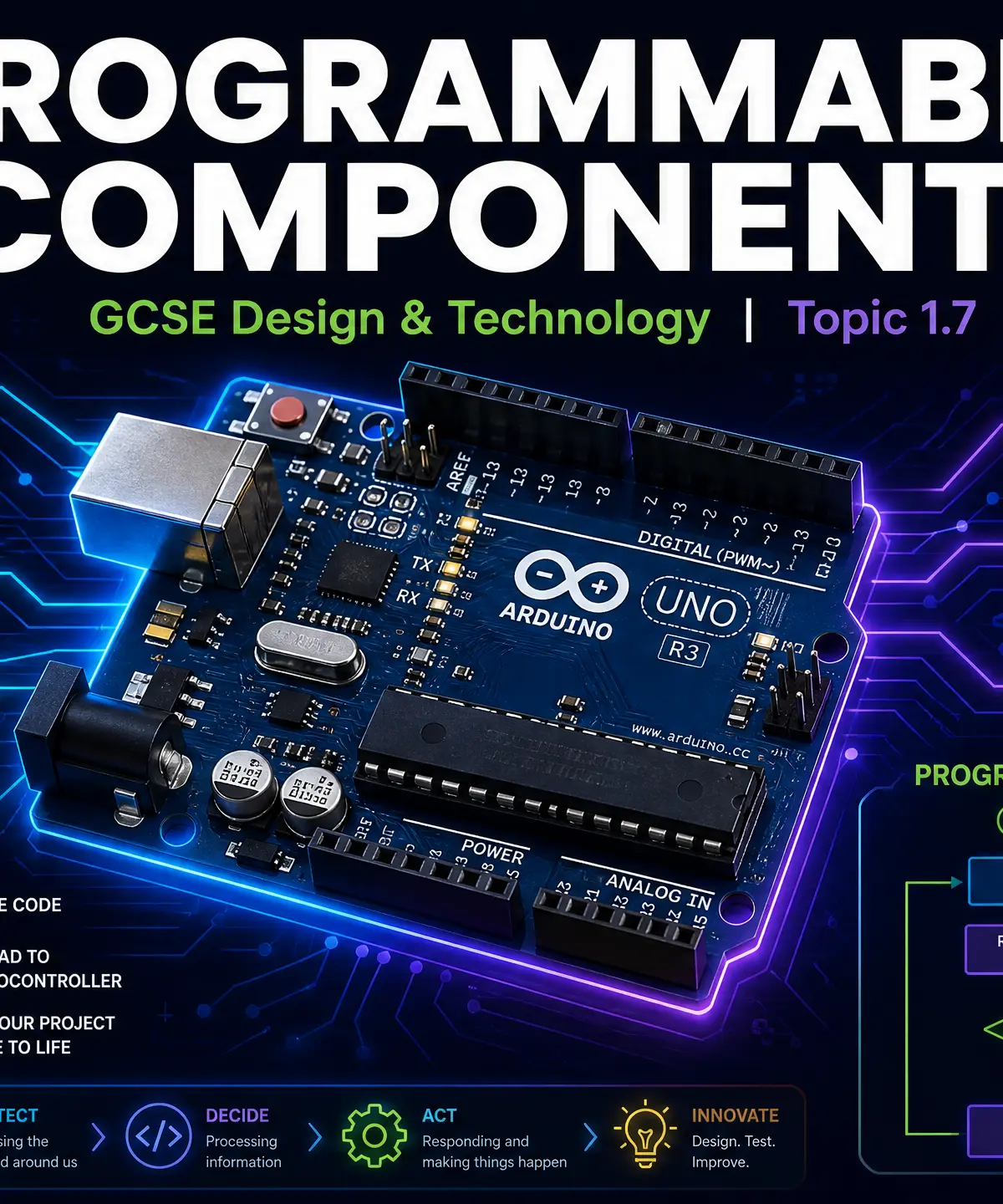
Programmable components are at the heart of modern product design. Instead of designing a product with fixed, hardwired behaviour, designers use microcontrollers to embed intelligence and functionality. This allows products to sense their environment, make decisions, and respond dynamically. Whether it's an automatic nightlight, a smart thermostat, or a robotic arm, understanding how to program and integrate these components is essential for GCSE Design and Technology.
Listen to the revision podcast for a comprehensive overview of this topic:

Key Knowledge & Theory
Core Concepts
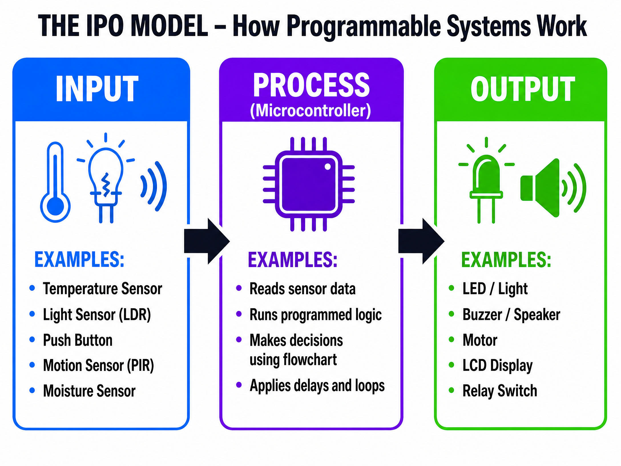
The IPO ModelThe fundamental framework for all programmable systems is the Input-Process-Output (IPO) model. Examiners expect you to use this structure when explaining how any smart product works.
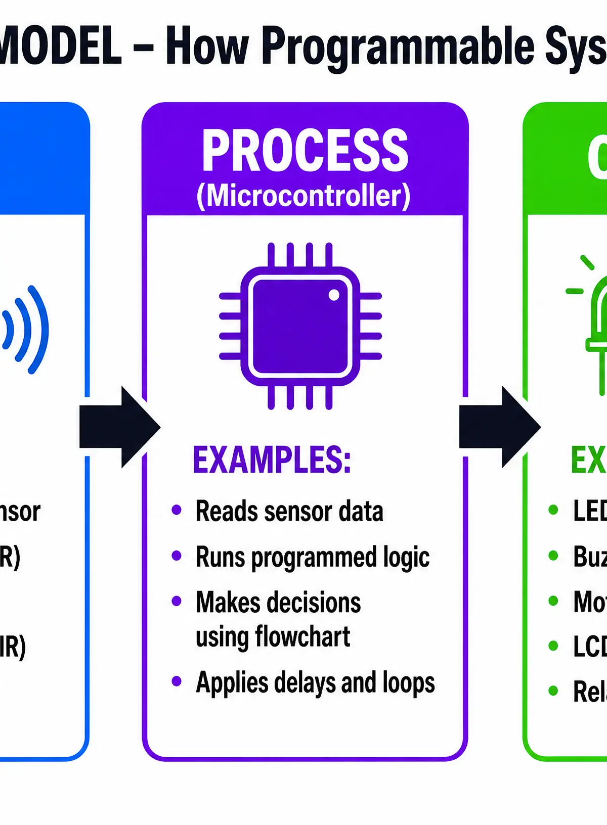
- Input: Information gathered from the physical world using sensors.
- Process: The microcontroller receives the input data, runs through its programmed logic (represented by a flowchart), and makes a decision.
- Output: The microcontroller sends a signal to an actuator to perform a physical action.
Analogue vs. Digital InputsCandidates frequently lose marks by confusing these two types of signals:
- Digital inputs have only two states: ON or OFF (1 or 0). Examples include push buttons, toggle switches, and microswitches.
- Analogue inputs have a continuous range of values. Examples include Light Dependent Resistors (LDRs), thermistors (temperature sensors), and moisture sensors. The microcontroller uses an Analogue-to-Digital Converter (ADC) to read these values.
Key Components
| Component Type | Name | Function | Example Application |
|---|---|---|---|
| Input (Sensor) | LDR (Light Dependent Resistor) | Detects light intensity | Automatic streetlights |
| Input (Sensor) | Thermistor | Detects temperature changes | Smart heating thermostat |
| Input (Sensor) | PIR (Passive Infrared) | Detects motion/heat signatures | Security alarms |
| Process | Microcontroller (e.g., PIC, Arduino) | The 'brain' that runs the program | Controlling a washing machine cycle |
| Output (Actuator) | LED (Light Emitting Diode) | Provides visual indication | Status lights on a router |
| Output (Actuator) | Piezo Buzzer | Generates sound | Microwave cycle finished alarm |
| Output (Actuator) | Servo Motor | Provides precise rotational movement | Robotic arm joint |
Technical Vocabulary
- Microcontroller: A compact integrated circuit designed to govern a specific operation in an embedded system.
- Actuator: A component that turns electrical energy into physical movement or action.
- Logic: The sequence of instructions and decisions programmed into the microcontroller.
- Algorithm: A step-by-step set of operations to be performed.
Practical Skills
Techniques & Processes: Flowcharts
Flowcharts are the standard method for planning and documenting the logic of a programmable system. You must be able to draw them accurately and interpret them in the exam.
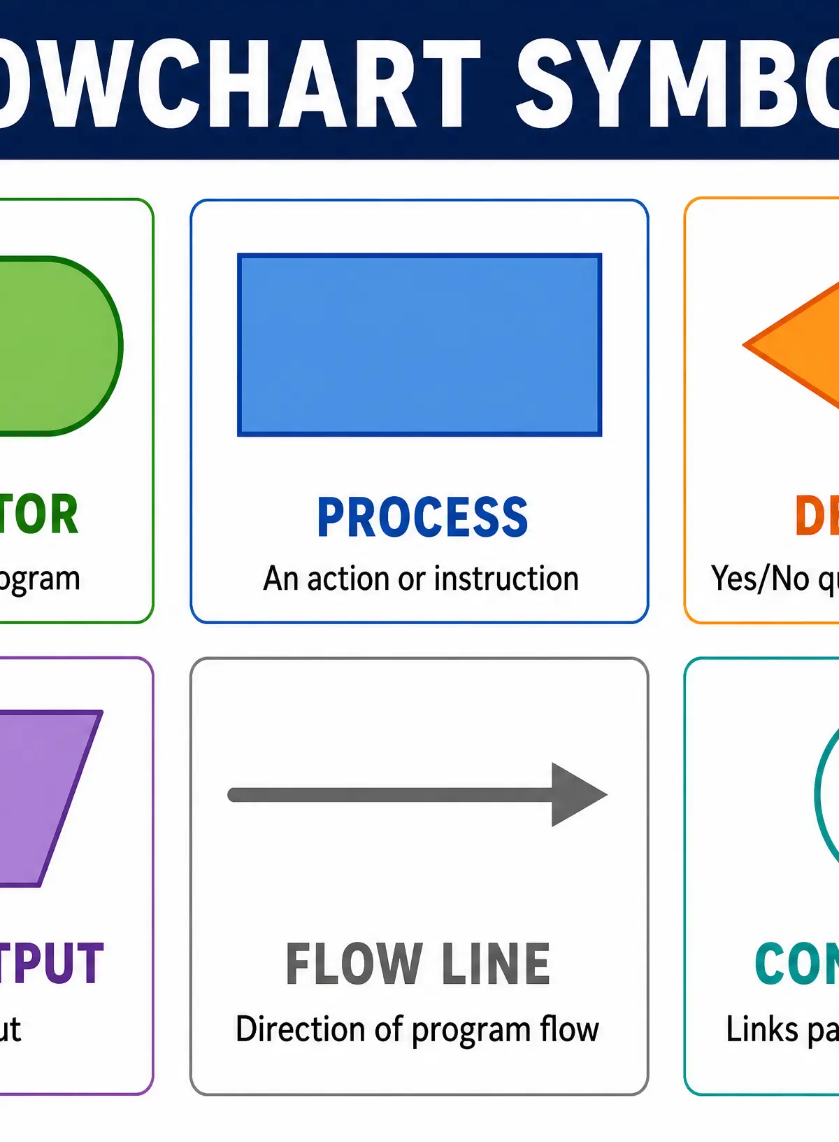
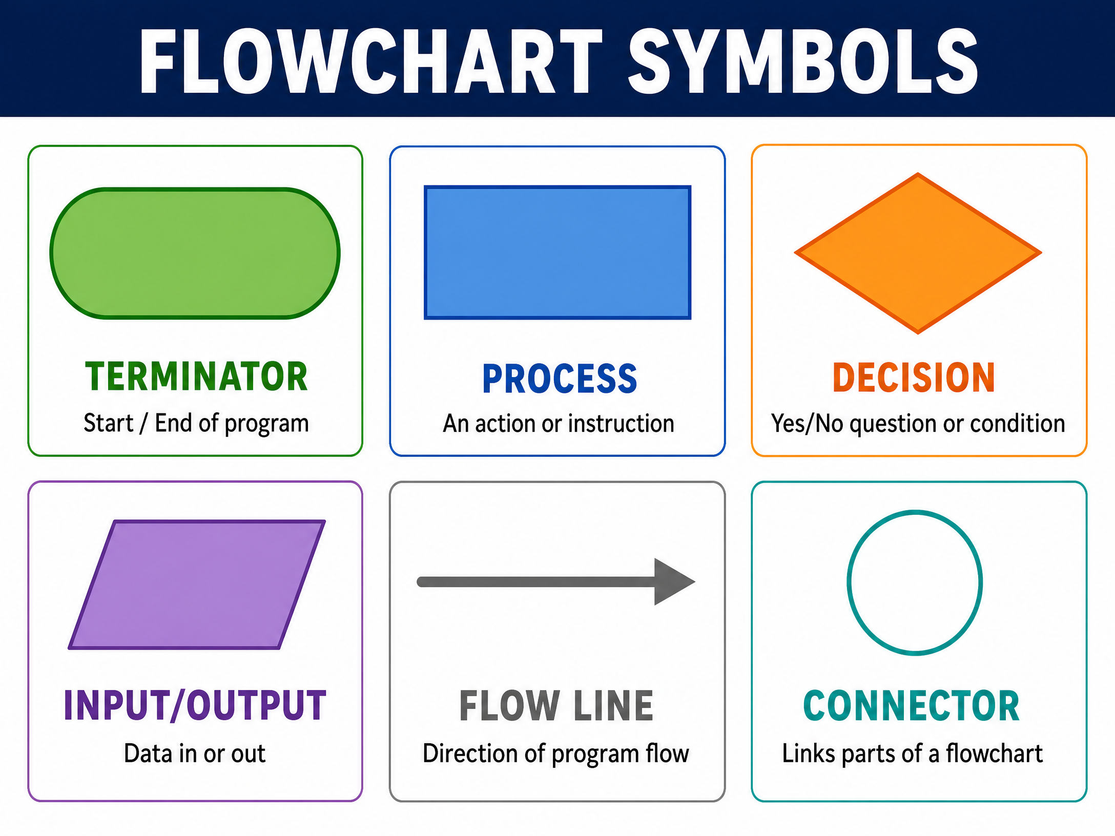
Standard Symbols:
- Terminator (Oval): Start or End.
- Process (Rectangle): An instruction or action (e.g., "Turn on LED", "Wait 5s").
- Decision (Diamond): A yes/no question (e.g., "Is button pressed?").
- Input/Output (Parallelogram): Data entering or leaving the system.
Programming Structures:
- Loops: Repeating a section of code (shown by an arrow looping back).
- Delays: Pausing the program (shown in a process box).
- Counts: Tracking how many times an event occurs.
Materials & Equipment
When building practical projects, you will use prototyping boards (like breadboards) to test circuits before soldering. You must ensure correct polarity for components like LEDs (the long leg is the anode/positive) and use appropriate resistors to prevent blowing components.
Portfolio/Coursework Guidance
Assessment Criteria
For your Non-Examined Assessment (NEA), embedding a programmable component can elevate your product into the higher mark bands. Examiners look for:
- Justification: Why does the product need a microcontroller? Does it genuinely enhance functionality?
- Development: Evidence of testing the code (e.g., screenshots of simulation software or flowcharts with annotations).
- Integration: How well the electronics are housed safely and neatly within the physical casing.
Building a Strong Portfolio
- Include your flowcharts in your design development section.
- Take photos of your breadboard prototypes.
- Annotate your code: explain why you chose specific delay times or sensor thresholds.
- Evaluate the success of the programming: did it respond fast enough? Was the sensor too sensitive?
Exam Component
Written Exam Knowledge
You will face questions ranging from 1-mark multiple choice (e.g., identifying a flowchart symbol) to 6-8 mark extended response questions where you must design a control system for a specific context.
Exam Preparation
Practise writing out the IPO model for everyday objects. Look at a microwave, a toaster, or an automatic door, and try to sketch the flowchart that controls it.
Interactive Diagrams
1 interactive diagram to visualise key concepts
Conceptual Flow Outline
Flowchart for an automatic nightlight
Worked Examples
2 worked examples — open one to explore the question and available guidance.
Practice Questions
Test your understanding — click to reveal model answers
Identify the standard flowchart shape used for a decision.
Hint: Think about the shape that allows lines to branch off in two different directions (Yes/No).
Explain the difference between an analogue input and a digital input, giving one example of a component for each.
Hint: Think about continuous ranges versus fixed states.
A designer is creating an automated pet feeder. It must dispense food when a button is pressed, OR automatically dispense food at 8:00 AM every day. Explain how programmable components make this product more successful than a purely mechanical solution.
Hint: Focus on flexibility, decision-making logic, and the ability to handle multiple different inputs.